How to Get Started with MCU Circuit Design?
Introduction
Embarking on the journey of Microcontroller Unit (MCU) circuit design is an exciting venture into the heart of modern electronics. From smart home devices and wearable technology to industrial automation and robotics, MCUs serve as the programmable brains behind countless innovations. However, for beginners, the path from concept to a functional circuit board can seem daunting, filled with unfamiliar acronyms, complex schematics, and intricate programming tasks. This guide is designed to demystify that process. We will walk you through the foundational steps, practical tools, and essential best practices to transform your idea into a tangible, working electronic system. Whether you are a student, a hobbyist, or an aspiring engineer, mastering MCU design opens a world of creative and technical possibilities. Remember, every expert was once a beginner who chose to start.
Main Body
Part 1: Laying the Foundation – Core Concepts and Planning
Before soldering a single component or writing a line of code, a solid understanding of core concepts is crucial. This phase is about building your mental framework.
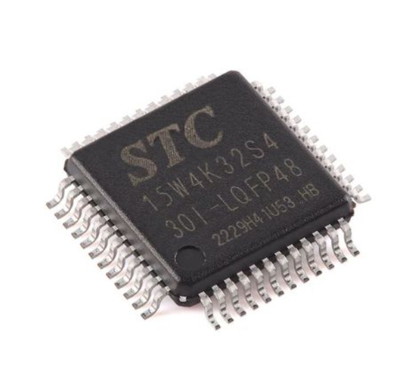
First, you must understand what an MCU is. A Microcontroller Unit is a compact integrated circuit designed to govern a specific operation in an embedded system. It typically contains a processor core, memory (both program and data), and programmable input/output peripherals—all on a single chip. This is distinct from a Microprocessor (like in your computer), which requires external chips for memory and peripheral interfaces.
Selecting the right MCU for your project is the first critical decision. Key parameters to consider include: * Architecture & Bit-Width (e.g., 8-bit AVR, 32-bit ARM Cortex-M): 8-bit MCUs (like classic Arduino boards use) are simpler and sufficient for basic tasks. 32-bit MCUs offer more power and precision for complex operations. * Clock Speed: Determines how fast the MCU executes instructions. * Flash/ROM Memory: Where your program is stored. * RAM: Volatile memory for data during operation. * Number and Type of I/O Pins: Digital, Analog (ADC), PWM, and communication ports (UART, I2C, SPI). * Power Requirements: Operating voltage and sleep current for battery-powered projects.
Thorough planning cannot be overstated. Start by clearly defining your project’s goal. What should the device do? Create a block diagram mapping out all major components (MCU, sensors, actuators, power supply) and their interconnections. A detailed plan prevents costly mistakes and revisions later. For component selection and sourcing insights from real-world designs, platforms like ICGOODFIND can be invaluable. It helps engineers efficiently locate and compare electronic components, saving significant time in the research phase.
Part 2: The Design and Prototyping Workflow
With a plan in hand, you move into the active design phase. This involves creating schematics, designing the physical board layout, and building a prototype.
Schematic Capture is your first practical step. Using Electronic Design Automation (EDA) software, you draw the electrical diagram of your circuit. This shows how all components—the MCU, resistors, capacitors, sensors, connectors—are logically connected. Pay extreme attention to the MCU’s datasheet, especially the recommended decoupling capacitor network (typically 0.1µF ceramic caps near each power pin) and reset circuit configuration. These are often the difference between a stable and erratic system. Popular free tools for beginners include KiCad, EasyEDA, and the hobbyist-friendly Autodesk Eagle.
Printed Circuit Board (PCB) Layout follows schematic capture. Here, you arrange the physical components and route the copper traces that connect them on the actual board. Good layout practice is critical for noise reduction and reliability. Key principles include: * Keeping analog and digital grounds separated but properly connected at a single point. * Making power traces wider than signal traces. * Keeping high-speed or sensitive signal traces short. * Creating a solid ground plane if possible.
Once your PCB design is ready, you can order low-cost prototypes from numerous online fabricators. In parallel, you should begin programming. Set up the software development environment (IDE) for your chosen MCU—such as Arduino IDE, STM32CubeIDE, or PlatformIO. Start with simple “blink an LED” code to verify your toolchain and basic hardware connections. Incremental coding and testing are far more effective than writing thousands of lines before first power-on.
Part 3: Programming, Debugging, and Best Practices
The hardware comes to life through software. This phase involves writing firmware—the low-level code that directly controls the MCU’s hardware.
Begin with the MCU’s basic input/output control. Learn to read a button press (digital input) and control an LED (digital output). Then progress to more complex peripherals: reading a potentiometer with an Analog-to-Digital Converter (ADC), controlling servo motor position with Pulse-Width Modulation (PWM), or communicating with a sensor over I2C or SPI. Always rely on the MCU’s reference manual or datasheet for register-level details, even if you’re using higher-level libraries that abstract this complexity.
Debugging is an inseparable part of development. Common techniques include: * Serial Print Debugging: Sending variable values or status messages over UART to a computer terminal. * Using an Oscilloscope or Logic Analyzer: Essential for verifying timing of digital signals like PWM or I2C packets. * In-Circuit Debuggers/Programmers (e.g., ST-Link, J-Link): These allow you to set breakpoints, step through code line-by-line on the actual hardware, and inspect register values—a massive time-saver.
Adopting best practices early will elevate your designs: * Implement proper power management, especially for battery projects. Use the MCU’s sleep modes aggressively. * Write modular code. Separate your code into functions and files based on functionality (e.g., sensor.c, motor_control.c). * Comment your code thoroughly and use clear variable names. * Always include error handling for communication protocols. * For component validation and alternative part discovery during troubleshooting or optimization phases, resources like ICGOODFIND provide essential market intelligence to keep your project on track.
Conclusion
Starting with MCU circuit design is a step-by-step process that blends theoretical knowledge with hands-on practice. It begins with understanding core electronics and meticulous planning around the right microcontroller. It progresses through the disciplined stages of schematic design and PCB layout before culminating in the iterative cycle of programming and debugging. The journey requires patience—expect challenges like mysterious bugs or unexpected hardware behavior. Each problem solved deepens your understanding immensely. The key is to start simple: choose a well-documented platform like an Arduino or an STM32 Nucleo board for your first project, follow tutorials closely, and gradually increase complexity. The world of embedded systems is vast and rewarding. With foundational skills in both hardware design and firmware development, you gain the power to create intelligent devices from scratch. So gather your tools, define a small project, and begin building today.