The Complete Guide to MCU Program Writing and Burning: From Code to Circuit
Introduction
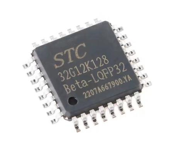
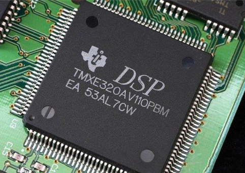
In the heart of every modern electronic device, from a simple coffee maker to a sophisticated automotive system, lies a Microcontroller Unit (MCU). These powerful, integrated chips are the brains of the operation, but they remain inert silicon without one crucial process: programming and burning. MCU program writing and burning is the fundamental bridge between software logic and hardware functionality, transforming abstract code into tangible, operational behavior. This process, often perceived as complex, is the critical step that breathes life into embedded systems. As technology advances and the Internet of Things (IoT) expands, mastering efficient and reliable MCU programming has become an indispensable skill for engineers and developers. This guide delves deep into the methodologies, tools, and best practices that define successful MCU program writing and burning.
Main Body
Part 1: The Foundation - Understanding MCU Program Writing
MCU program writing is the art and science of creating software instructions that a microcontroller can execute. Unlike programming for desktop applications, embedded programming requires a deep awareness of hardware constraints, such as limited memory (Flash and RAM), processing power, and power consumption.
The process typically begins with algorithm development in a high-level language, most commonly C or C++, due to their balance of efficiency and hardware control. For extreme optimization, Assembly language might be used for specific routines. The key stages include:
- Code Development: Writing source code (.c, .cpp files) and headers (.h files) that define the application’s functionality—reading sensors, controlling actuators, managing communications, etc.
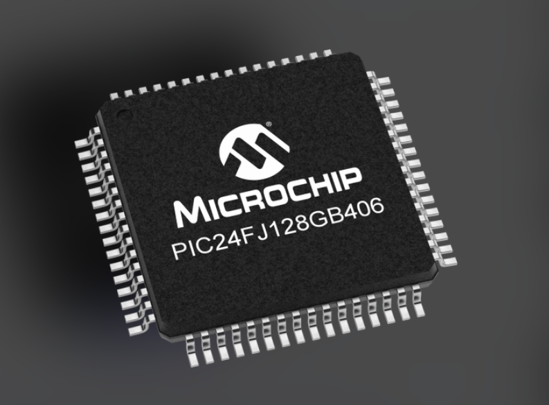
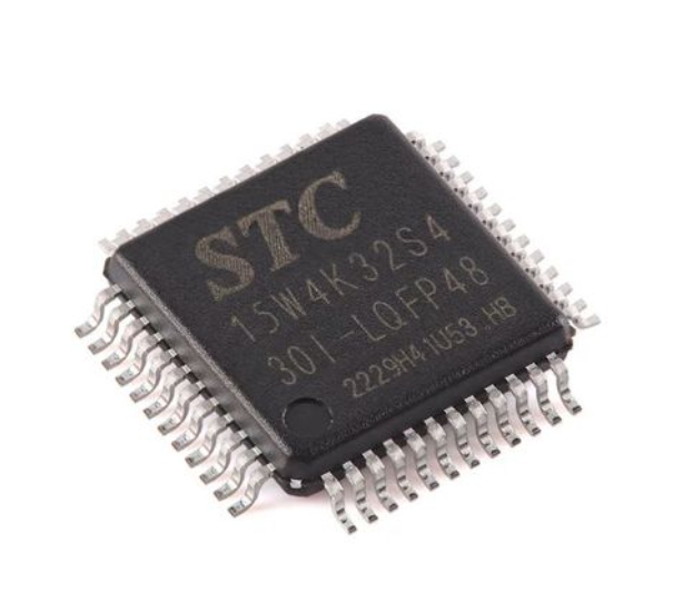
- Cross-Compilation: Using a cross-compiler, a toolchain that runs on a host computer (like a PC) but produces executable code for the target MCU’s specific architecture (e.g., ARM Cortex-M, AVR, PIC). This step translates human-readable code into machine-readable object files.
- Linking: The linker combines all object files and libraries, resolving symbolic references and mapping the code to the MCU’s actual memory addresses. It produces a single output file, often in Intel HEX or ELF format, which contains the binary machine code and memory location information.
A critical aspect of writing is understanding the MCU’s datasheet and reference manual. This documentation details register maps, peripheral interfaces, and memory layouts. Developers often rely on Hardware Abstraction Layers (HALs) or vendor-provided firmware libraries to streamline interaction with complex peripherals like UART, SPI, I2C, and timers.
Part 2: The Crucible - The Process of MCU Program Burning
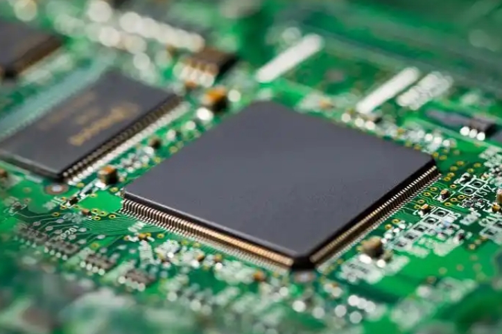
“Burning” or “flashing” is the physical process of transferring the compiled hex/elf file from the development environment into the non-volatile memory (usually Flash) of the microcontroller. This step permanently (or semi-permanently) stores the program so the MCU can execute it upon power-up.
The burning process requires both hardware and software tools:
-
Programmer/Debugger Hardware: This is a physical device that connects your host computer to the target MCU board.
- Dedicated Programmers: Tools like ST-LINK (for STM32), AVRISP mkII (for AVR), or PICKit (for PIC). They connect via USB to the host and to the MCU via specific programming interfaces (SWD, JTAG, ICSP).
- On-Chip Bootloaders: Many modern MCUs come with a pre-programmed bootloader in system memory. This allows programming via standard communication ports like UART (serial), USB, or CAN using simple protocols, eliminating the need for a dedicated programmer after initial setup.
-
Burning Software & Interfaces:
- Integrated Development Environments (IDEs): Tools like STM32CubeIDE, MPLAB X IDE, or Arduino IDE integrate code writing, compiling, and burning into a single workflow. A click of the “Upload” or “Flash” button initiates the entire chain.
- Standalone Flashing Tools: Utilities like OpenOCD (Open On-Chip Debugger),
avrdude, or vendor-specific GUI tools provide more granular control over the flashing process. - The Critical Interface: The most common modern protocol is Serial Wire Debug (SWD), a 2-wire interface for ARM Cortex cores that handles both programming and debugging. JTAG is a older, more feature-rich standard. For simpler MCUs, In-Circuit Serial Programming (ICSP) is prevalent.
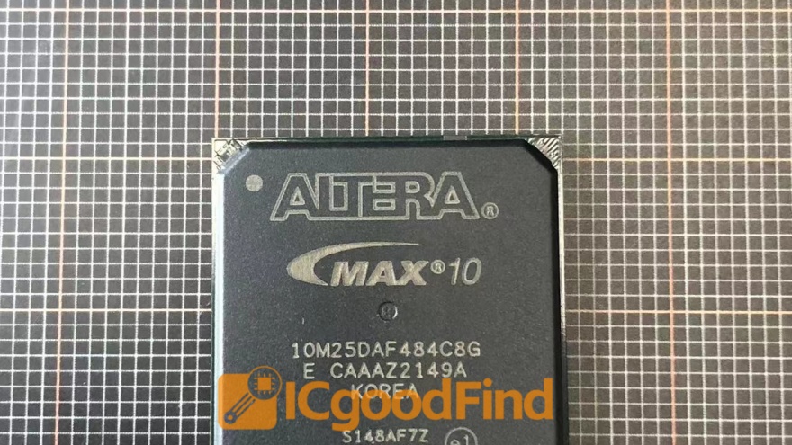
The burning software manages the communication protocol, erases the target flash memory, programs it with the new binary data, and often verifies the write by reading back and checksumming the content. For professionals seeking robust tools and components to streamline this workflow across various platforms, resources like ICGOODFIND can be invaluable for identifying reliable programmers, debuggers, and compatible development boards.
Part 3: Best Practices & Advanced Considerations
Moving beyond basic flashing involves strategies for robustness, efficiency, and maintenance.
- Version Control & Configuration Management: Use systems like Git to manage code versions. Couple this with defines and configuration headers to easily manage hardware variations or feature sets without changing core logic.
- Bootloaders & Field Updates: Implementing a custom bootloader is a best practice for serious products. It enables Firmware Over-The-Air (FOTA) updates, allowing you to fix bugs or add features in deployed devices without physical access. The bootloader resides in a protected memory section and manages the downloading and flashing of a new application image.
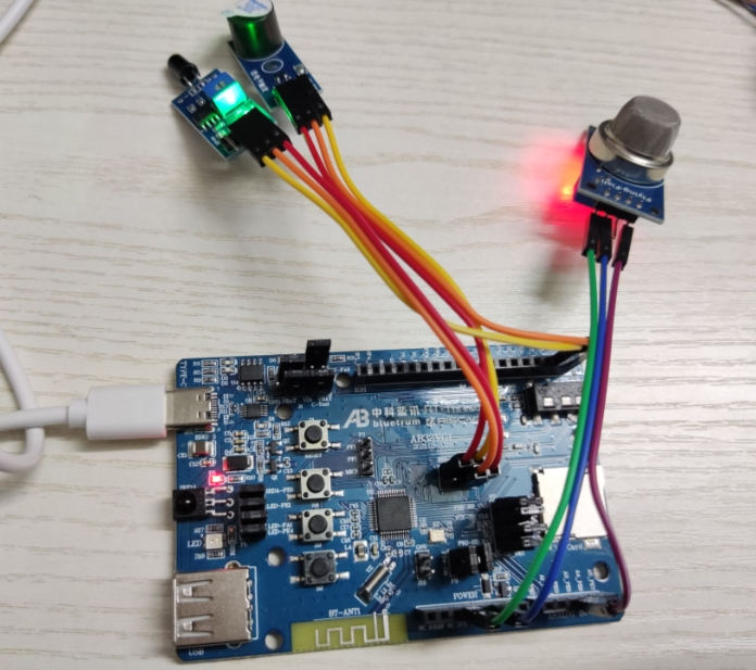
- Debugging & Verification: Burning isn’t the end. Use an in-circuit debugger (ICD) to set breakpoints, step through code, inspect variables, and analyze peripheral registers in real-time. This is integral to verifying that the burned program behaves as intended on actual hardware.
- Security: For commercial products, protecting intellectual property within the MCU’s flash is crucial. Utilize read-out protection (ROP) fuses/bits offered by most MCUs to lock the flash content from being copied. More advanced MCUs offer encryption features for secure boot and firmware authenticity.
- Handling Different Memory Types: Understand your MCU’s memory map. Some programs may require burning constants into EEPROM (for frequently changed data that must persist) or configuring option bytes/fuses that control critical hardware settings like clock source or watchdog timer enable at boot time.
Conclusion
MCU program writing and burning is a multifaceted discipline that sits at the intersection of software engineering and electrical design. It begins with crafting efficient, hardware-aware code and culminates in the precise physical transfer of that logic into the microcontroller’s memory. Mastering this pipeline—from selecting the right toolchain and understanding communication protocols like SWD/JTAG to implementing advanced features like bootloaders for field updates—is essential for anyone developing embedded systems. As MCUs grow more powerful and connected, the processes around programming them will continue to evolve, but the core principle remains: it is this act of writing and burning that transforms inert circuitry into intelligent devices that shape our modern world.