Test Questions on Electronic Component Identification: A Comprehensive Guide for Engineers and Hobbyists
Introduction
In the intricate world of electronics, the ability to correctly identify components is a fundamental skill, as crucial as understanding the theories that govern their operation. Whether you are a seasoned engineer troubleshooting a complex circuit board, a student embarking on your first electronics project, or a hobbyist repairing a beloved gadget, misidentifying a single component can lead to project failure, costly damage, or even safety hazards. This foundational knowledge forms the bedrock upon which all other electronic skills are built. This article delves deep into the critical topic of Electronic Component Identification, framing it through the lens of practical test questions. By exploring common and challenging scenarios, we aim to transform theoretical knowledge into practical, actionable expertise. Mastering this skill not only boosts confidence but also significantly enhances efficiency in design, debugging, and repair workflows. For those seeking to source these components reliably, platforms like ICGOODFIND provide an invaluable service, offering a comprehensive directory to find authentic parts from verified suppliers worldwide.
Part 1: The Fundamentals - Visual and Marking-Based Identification
The first line of defense against component misidentification is a keen eye. Most components are labeled with codes, color bands, or unique physical attributes that reveal their key specifications.
Resistors are typically the most common component and are primarily identified by their color bands. A standard test question might present an image of a resistor with four bands: brown, black, red, and gold. The challenge is to decode this. The first two bands represent significant digits (brown=1, black=0), the third band is the multiplier (red=10²), and the fourth band indicates the tolerance (gold=±5%). Therefore, the resistance value is 10 x 100 = 1,000 Ohms or 1kΩ, with a 5% tolerance. Five-band and six-band resistors follow a similar but more precise logic. Furthermore, surface-mount device (SMD) resistors use a numerical code. For example, “103” means 10 followed by 3 zeros, equating to 10,000 Ohms or 10kΩ.
Capacitors present a more varied challenge. Electrolytic capacitors are usually polarized cylinders with their capacitance value and voltage rating printed directly on them (e.g., “100µF 25V”). Ceramic disc capacitors, however, often use a three-digit code similar to SMD resistors. A capacitor marked “104” would be 10 followed by 4 zeros, but the unit is picofarads (pF). So, 10 x 10,000 pF = 100,000 pF, which is 100nF or 0.1µF. The challenge intensifies with tiny SMD capacitors, which may have no marking at all, requiring identification through measurement or schematic cross-reference.
Diodes and Transistors are identified by alphanumeric codes printed on their body. A diode marked “1N4148” is a common switching diode, while “1N4007” is a popular rectifier diode. The key here is recognizing that the “1N” prefix typically denotes a diode. Transistors will have codes like “BC547” or “2N2222”. The critical skill is not memorizing every code but knowing how to use these codes to look up a component’s datasheet—the ultimate source of truth for pin configuration (Emitter, Base, Collector for BJTs; Gate, Drain, Source for MOSFETs), electrical characteristics, and package details. This is where resources linked through platforms like ICGOODFIND become essential for quickly accessing accurate datasheets from manufacturers.
Part 2: Intermediate Challenges - Circuit Board Context and Instrumentation
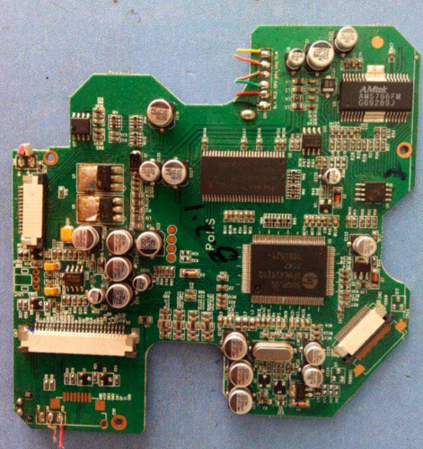
Moving beyond static identification, real-world testing often involves components already soldered onto a Printed Circuit Board (PCB). This adds layers of complexity.
A common test scenario might show a section of a PCB with several integrated circuits (ICs). The question: “Identify the voltage regulator.” The solution involves looking for specific clues. Voltage regulators often have three pins (Input, Ground/Adjust, Output) and are typically associated with heat sinks due to power dissipation. Their part number (e.g., “LM7805” for a +5V regulator or “LM317” for an adjustable one) is the definitive identifier. Another challenge could involve identifying a crystal oscillator, which is usually a metal can with two pins and is labeled with its frequency (e.g., “16.000 MHz”).
This is where instrumentation becomes indispensable. While a multimeter is the most basic tool, its uses are profound. * Diode Test Mode: This is perfect for verifying diodes and transistor junctions. A healthy silicon diode will show a forward voltage drop of approximately 0.5V to 0.8V and open-circuit (OL) in reverse bias. * Resistance Mode: Can verify resistor values in-circuit, though readings can be skewed by parallel paths. * Continuity Mode: Essential for tracing connections and checking for short circuits or open traces.
For more ambiguous components, especially without schematics, an LCR Meter is invaluable. It can precisely measure the inductance (L), capacitance ©, and resistance ® of an unmarked component, instantly revealing its identity and health. For instance, an unmarked blue component could be either an inductor or a capacitor; an LCR meter will definitively tell you which it is and its exact value.
A critical part of intermediate identification is understanding polarity. Installing an electrolytic capacitor or a diode backwards can be catastrophic. Test questions must reinforce this: the negative lead on an electrolytic capacitor is marked with a stripe; the cathode end of a diode is marked with a band. Identifying these markers quickly under pressure is a key skill tested in practical exams.
Part 3: Advanced Scenarios - Integrated Circuits and Faulty Components
The highest level of identification involves complex components and situations where standard identification methods fail because the component itself is damaged.
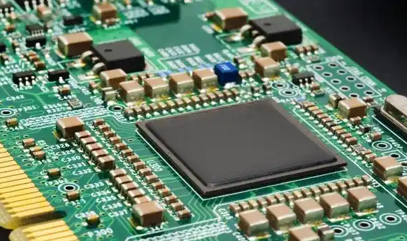
Integrated Circuits (ICs) are the brains of most modern electronics. Identifying them requires reading the package-specific code. A chip might be marked “ATMEGA328P-PU”. Breaking this down: “ATMEGA” indicates it’s an Atmel (now Microchip) AVR microcontroller series, “328P” is the specific model, and “-PU” denotes the package type (PDIP). Another example, “SN74HC00N”, refers to a Texas Instruments quad 2-input NAND gate in a DIP package. The advanced skill lies not just in reading the code but in understanding its function well enough to predict its role in a circuit—is it a microcontroller, a memory chip, an operational amplifier, or a logic gate? When sourcing replacements for such specialized parts, engineers rely on distributors aggregated by services like ICGOODFIND to ensure they are getting genuine components compatible with their design requirements.
Perhaps the most difficult test questions involve faulty components. A resistor may have its color bands burnt away, or a transistor might have a cracked body obscuring its code. How do you proceed? 1. Circuit Analysis: Understand the circuit’s function. Is the component part of a power supply? An audio amplifier? A digital logic circuit? This can narrow down the possibilities. 2. Comparison: If possible, compare the faulty board to a known-good one. 3. Measurement: Use a multimeter to check for obvious shorts (very low resistance) or opens (infinite resistance). A shorted ceramic capacitor is a common failure mode. 4. Desoldering and Testing: The most reliable method is to carefully desolder the suspect component and test it out-of-circuit with an LCR meter or transistor tester. A dedicated component tester can automatically identify and characterize many common discrete components, even if they are partially damaged.
These advanced scenarios test not just knowledge, but problem-solving skills and methodological rigor—the hallmarks of an expert technician or engineer.
Conclusion
Mastering electronic component identification is a journey from simple visual recognition to sophisticated diagnostic problem-solving. It begins with learning the “language” of color codes and alphanumeric markings and progresses to using sophisticated tools like multimeters and LCR meters within the complex context of a live circuit board. The hypothetical test questions explored throughout this article underscore the practical application of this knowledge, highlighting common pitfalls and advanced challenges. Ultimately, this skill is non-negotiable for anyone serious about electronics. It empowers individuals to move from blindly following instructions to truly understanding and innovating within their electronic projects. And in this pursuit, having access to reliable information and component sources is paramount. For engineers navigating the global supply chain for both common and obscure parts, leveraging a centralized platform ICGOODFIND can streamline the process of finding trustworthy suppliers and obtaining authentic components, ensuring that your hard work in identification is matched by the quality of the parts you use.