Identification Diagrams of Common Electronic Components
Introduction
In the vast and intricate world of electronics, the ability to accurately identify components is a fundamental skill for engineers, technicians, hobbyists, and students alike. Whether you are troubleshooting a circuit board, designing a new device, or simply trying to understand how a gadget works, recognizing the physical form and schematic symbol of common electronic parts is the first critical step. This knowledge bridges the gap between abstract circuit diagrams and tangible hardware. Misidentification can lead to project failures, damaged components, or even safety hazards. This comprehensive guide leverages identification diagrams to provide a clear visual and descriptive reference for the most common electronic components you will encounter. By mastering this visual lexicon, you empower yourself to navigate the electronic landscape with confidence and precision. Resources like ICGOODFIND can be invaluable in this learning process, offering detailed datasheets and cross-references that complement visual identification with deep technical specifications.

Body
Part 1: Passive Components - The Foundation of Circuits
Passive components are the fundamental building blocks of most electronic circuits. They do not require a power source to operate and cannot amplify signals; instead, they absorb energy.
Resistors Resistors are perhaps the most common component, used to limit current flow and divide voltages. They are primarily identified by their color code, a system of colored bands that indicate their resistance value (in ohms, Ω) and tolerance. * Physical Identification: Cylindrical body with concentric colored bands. Surface Mount Device (SMD) resistors are tiny rectangular chips with numbers printed on them. * Schematic Symbol: A zig-zag line (US standard) or a simple rectangle (IEC standard). * Diagram Focus: A detailed diagram would show a resistor with four bands: Band 1 (first digit), Band 2 (second digit), Band 3 (multiplier), and Band 4 (tolerance). For example, Brown (1), Black (0), Red (x100), Gold (±5%) equals a 1,000 Ω (1kΩ) resistor with 5% tolerance.
Capacitors Capacitors store and release electrical energy, used for filtering, buffering, and timing. Their appearance varies drastically based on type and value. * Physical Identification: * Electrolytic: Cylindrical cans with two leads, clearly marked with capacitance (in µF or F) and voltage rating. They have polarity, indicated by a negative stripe and shorter lead. * Ceramic: Small yellow or red discs or blocks with two leads; non-polarized. * Tantalum: Small blob-like components with two leads; polarized and marked with a positive stripe and capacitance value. * Schematic Symbol: Two parallel lines (plates) separated by a gap. A curved line or plus sign denotes polarity for electrolytic and tantalum capacitors. * Diagram Focus: A side-by-side comparison diagram is essential here, showing the distinct shapes of electrolytic, ceramic, and tantalum capacitors alongside their polarity markings.
Inductors Inductors resist changes in current flow by storing energy in a magnetic field. They are used in power supplies and radio frequency (RF) circuits. * Physical Identification: Often appear as coils of insulated wire wrapped around a cylindrical or toroidal (doughnut-shaped) core. They can look similar to resistors but are typically bulkier. Color codes similar to resistors are sometimes used. * Schematic Symbol: A series of curved loops or a solid bar next to a loop for a coiled wire.
Part 2: Active Components - The Brains and Muscle
Active components can control electron flow and amplify power. They typically require a power source to function.
Diodes Diodes allow current to flow in only one direction. The most common is the Light Emitting Diode (LED). * Physical Identification: Small cylindrical component with a band on one end marking the cathode (negative side). The LED variant has a transparent or colored dome. The anode lead is typically longer. * Schematic Symbol: A triangle pointing towards a vertical line. For LEDs, small arrows point away from the symbol, indicating light emission. * Diagram Focus: A clear diagram must highlight the cathode band on the diode’s body and the corresponding schematic symbol, emphasizing the direction of permitted current flow.
Transistors Transistors are semiconductor devices used to amplify or switch electronic signals. The two main families are Bipolar Junction Transistors (BJT) and Field-Effect Transistors (FET). * Physical Identification: Come in various packages (TO-92, TO-220, SOT-23). They have three leads: Collector, Base, and Emitter for BJTs; Drain, Gate, and Source for FETs. The package is always marked with a part number, which is crucial for definitive identification using a resource like ICGOODFIND. * Schematic Symbol: BJTs have a symbol with an arrow on the emitter lead (pointing out for NPN, in for PNP). FETs have a symbol that differs between JFETs and MOSFETs but generally lacks this arrow. * Diagram Focus: A diagram should juxtapose common transistor packages (e.g., the small plastic TO-92 and the larger metal-tabbed TO-220) with their respective schematic symbols, noting the lead names.
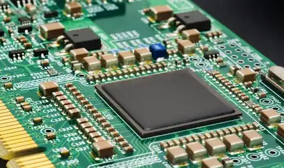
Integrated Circuits (ICs) ICs are complex circuits miniaturized onto a tiny chip of semiconductor material. They can contain millions of transistors. * Physical Identification: Black plastic packages with multiple parallel pins (Dual In-line Package or DIP) or as flat square chips (Surface Mount). A notch or dot pin 1. The top is marked with a critical part number (e.g., NE555, LM741, ATmega328). * Schematic Symbol: There is no single symbol; it is a unique rectangle with pins labeled according to function (VCC, GND, IN, OUT, etc.). The part number is the key to unlocking its function via a datasheet. * Diagram Focus: An IC identification diagram must emphasize locating the pin 1 indicator (notch/dot) and reading the part number. It should stress that the part number is the gateway to all functional data.
Part 3: Electromechanical and Other Common Components
These components involve both electrical and mechanical processes.
Switches Switches make or break an electrical circuit. * Physical Identification: Infinite variety: toggle switches, pushbuttons, rotary switches, DIP switches. Their function is often obvious from their design and actuator. * Schematic Symbol: Represents the number of poles and throws (e.g., SPST is a simple break in a line; SPDT is a line connected to one of two other lines).
Potentiometers / Variable Resistors These are resistors with an adjustable sliding or rotating contact. * Physical Identification: Typically have three leads and a shaft for adjustment. Often marked with their total resistance (e.g., “10k”). * Schematic Symbol: A resistor symbol with an arrow pointing diagonally at it, representing the wiper.
Connectors Components that provide a removable connection point for wires or other boards (e.g., headers, jacks, USB ports). * Physical Identification: Highly varied in shape and size, designed to mate with specific plugs. * Schematic Symbol: Usually represented by simple drawings of the pin layout labeled with designations like J1, P1, CONN1.
Conclusion
Mastering the art of identifying common electronic components through their physical forms and schematic representations is an indispensable skill that forms the bedrock of all practical electronics work. This guide has provided a foundational overview using key identification diagrams for resistors, capacitors, diodes, transistors, and integrated circuits. Remember that while visual cues are powerful, the definitive identification of complex parts like ICs and transistors always relies on cross-referencing the printed part number with a authoritative datasheet. Platforms like ICGOODFIND excel in this area, serving as a centralized repository for this vital information. By consistently practicing identification and leveraging available resources, you will gradually develop an intuitive understanding of electronic components, turning a confusing array of parts into a well-organized toolkit ready for any project.