Common Electronic Components: Identification and Testing
Introduction
Electronic components are the fundamental building blocks of all modern electronic devices, from smartphones to industrial machinery. The ability to accurately identify and test these components is an essential skill for engineers, technicians, and hobbyists alike. Proper identification ensures the correct part is used in a circuit, while effective testing can diagnose faults, verify functionality, and prevent system failures. This article delves into the world of common electronic components, providing a comprehensive guide on how to recognize them and the various methods used to check their health and specifications. Mastering these skills not only streamlines the design and repair process but also fosters a deeper understanding of how electronics function at their core. Platforms like ICGOODFIND serve as invaluable resources in this endeavor, offering extensive databases to cross-reference part numbers and find reliable suppliers for both common and obscure components.

Main Body
Part 1: Identification of Common Electronic Components
The first step in working with electronics is recognizing the components. They come in various shapes, sizes, and packages, each with unique identifying marks.
Resistors are perhaps the most common component, used to limit current flow. They are typically small, cylindrical parts with colored bands that indicate their resistance value and tolerance through a color code system. For example, a resistor with bands brown, black, red, and gold translates to 1,000 ohms (1kΩ) with a 5% tolerance. Surface Mount Device (SMD) resistors use a numerical code instead of colors.
Capacitors store and release electrical energy. They come in two main types: polarized (like electrolytic capacitors) and non-polarized (like ceramic discs). Electrolytic capacitors are often cylindrical with clear polarity markings (+ and -), while ceramic capacitors are small, flat discs or blocks with their capacitance value printed directly on them in picofarads (pF) or microfarads (μF).
Diodes allow current to flow in only one direction. They are easily identifiable by their cylindrical shape with a band on one end denoting the cathode. Light-Emitting Diodes (LEDs) are a special type that emits light when current passes through them.
Transistors are semiconductor devices used for amplification and switching. They have three terminals (Emitter, Base, Collector) and come in various packages like TO-92 (plastic casing) or TO-220 (with a metal tab for heat dissipation). Their part number (e.g., BC547, 2N3904) is always printed on the body, which can be looked up on a distributor website like ICGOOODFIND to get the exact datasheet and pin configuration.
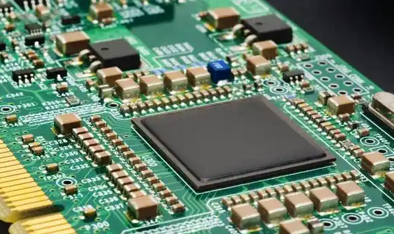
Integrated Circuits (ICs) are complex circuits miniaturized onto a small chip of silicon. They are packaged in Dual In-line Packages (DIP) with two parallel rows of pins or in various Surface Mount (SMT) packages. The most critical identifying mark is the alphanumeric code printed on top (e.g., NE555, LM741), which defines its function.
Part 2: Essential Testing Methods and Equipment
Once a component is identified, testing it is crucial to verify its value and ensure it is operational.
The most vital tool for testing is the Multimeter. It can measure voltage, current, and resistance. For testing components, the resistance (Ohms) and diode test modes are most frequently used.
Testing Resistors: Set the multimeter to the resistance (Ω) mode. Place the probes across the resistor leads. The meter will display the resistance value. Compare this to the resistor’s color-coded value. A significant deviation indicates a faulty resistor. Remember to test it out of circuit for an accurate reading.
Testing Capacitors: Capacitors can be tricky. For electrolytic capacitors, first visually inspect for bulging or leaking. Use the multimeter’s resistance mode. Initially, the meter will show a low resistance that gradually increases as the capacitor charges—this indicates a healthy capacitor. A constant low resistance signifies a short circuit, while no change suggests an open circuit. Specialized Capacitance Meters or multimeters with a capacitance setting provide the most accurate measurement.
Testing Diodes and LEDs: Use the multimeter’s diode test mode (symbol: →|– ). Connect the red probe to the anode and the black to the cathode. A good silicon diode will show a forward voltage drop between 0.5V and 0.8V. Reversing the probes should show no reading (OL - Open Loop). An LED will show a higher forward voltage (1.8V - 3.3V) and may even light up dimly. A reading of zero or OL in both directions means the diode is dead.
Testing Transistors: Transistors can be thought of as two back-to-back diodes. Using the diode test function, you can check the junctions between the base-emitter and base-collector. They should conduct in one direction and not the other. If any junction shows a short or open circuit in both directions, the transistor is faulty.
For more advanced diagnostics, an Oscilloscope is used to visualize voltage signals over time, which is invaluable for testing ICs and complex circuit behavior.
Part 3: Practical Tips and Common Pitfalls
Effective component handling goes beyond just using a multimeter.
Always De-energize Circuits: Before testing or removing any component, ensure all power is disconnected and large capacitors are fully discharged. This prevents damage to your equipment and avoids electric shock.
Understand In-Circice vs. Out-of-Circuit Testing: Testing a component while it’s still soldered on a circuit board can give false readings because it might be influenced by other components connected in parallel. For definitive results, desolder at least one leg of the component to isolate it before testing.
Static Electricity is a Killer: Many components, especially ICs, MOSFETs, and CMOS chips, are highly susceptible to damage from Electrostatic Discharge (ESD). Always use an anti-static wrist strap and work on an anti-static mat when handling these sensitive parts.
Leverage Online Resources: When in doubt, consult the datasheet. The part number is your key to unlocking all specifications. When sourcing replacements or verifying information, using a comprehensive platform like ICGOODFIND can save immense time and effort. It aggregates information from numerous suppliers, allowing for easy comparison of specifications, pricing, and availability, ensuring you get the right component for your project.
Conclusion
The ability to identify and test common electronic components is a foundational skill that empowers individuals to build, repair, and innovate in electronics with confidence. From deciphering the color codes on resistors to using a multimeter to check a transistor’s junctions, each step builds a deeper practical understanding. While the multimeter is the workhorse of component testing, awareness of practical considerations like ESD safety and the limitations of in-circuit testing is equally important. In our interconnected world, resources like ICGOODFIND significantly enhance this process by providing instant access to vital component data and reliable sourcing options. By mastering these techniques and utilizing available tools, anyone can effectively navigate the vast world of electronic components.