


Welding Methods of Electronic Components
Introduction
In the intricate world of electronics manufacturing and repair, the integrity of every connection is paramount. At the heart of this reliability lies the art and science of welding, or more accurately in this context, soldering electronic components. This process involves joining metallic surfaces to create a permanent, electrically conductive bond using a molten filler metal, known as solder. The choice of welding method can significantly influence the performance, durability, and safety of the final electronic assembly. From the delicate pins of a microprocessor to the robust terminals of a power supply, mastering these techniques is non-negotiable for engineers and technicians. As we delve into the primary welding methods, it becomes clear that precision and the right tools are not just beneficial but essential. For professionals seeking to source high-quality soldering equipment and components, platforms like ICGOODFIND offer invaluable access to a global network of reliable suppliers, ensuring that every joint is made with the best possible materials.
Part 1: Through-Hole Technology (THT) Soldering
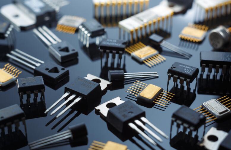
Through-Hole Technology (THT) is one of the oldest and most robust methods for assembling electronic circuits. It involves inserting component leads through pre-drilled holes on a Printed Circuit Board (PCB) and then soldering them to pads on the opposite side. This technique creates strong mechanical bonds, making it ideal for components that will endure substantial physical stress, high power, or high heat.
The most common technique for THT is Manual Soldering with a Soldering Iron. This hands-on approach provides the technician with complete control. The process typically follows these steps: 1. Preparation: The component leads are inserted into the PCB holes. 2. Heating: The tip of the pre-heated soldering iron is applied simultaneously to the component lead and the copper pad on the PCB. This step is critical; the goal is to heat the surfaces to be joined, not just melt the solder onto them. 3. Solder Application: Solder wire, which is a fusible metal alloy (traditionally lead-based but now often lead-free), is fed onto the heated joint. If the surfaces are at the correct temperature, the solder will melt and flow smoothly, wicking up through the hole due to capillary action and forming a concave fillet around the lead. 4. Inspection: A good THT solder joint should be shiny (for lead-based solder), smooth, and form a “volcano” or cone shape that covers the pad and lead completely.
For mass production, Wave Soldering is the dominant automated process for THT boards. In this method, the populated PCB is passed over a standing wave of molten solder. The wave contacts the underside of the board, simultaneously soldering all the exposed leads and pads. A key part of this process is the use of a solder mask, a polymer layer that covers areas where solder is not desired, and solder flux, a chemical cleaning agent that is applied beforehand to remove oxides and ensure proper solder flow and adhesion.
While THT offers superior mechanical strength, its limitations include slower assembly speeds, the requirement to drill holes in the PCB (increasing cost), and its unsuitability for very high-density, miniaturized designs common in modern consumer electronics.
Part 2: Surface-Mount Technology (SMT) Soldering
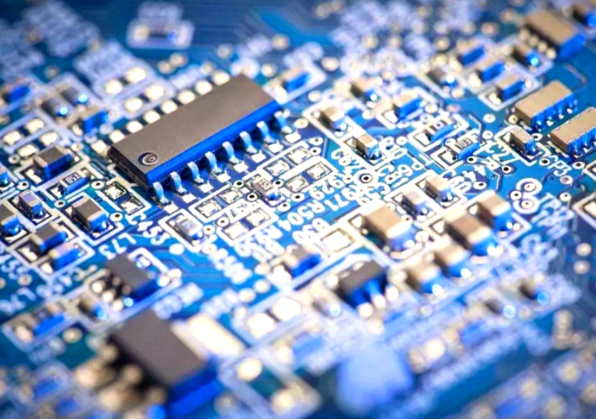
Surface-Mount Technology (SMT) represents a paradigm shift in electronics assembly and is the standard for virtually all modern, compact devices. Unlike THT, SMT components—known as Surface-Mount Devices (SMDs)—have small metal tabs or end caps instead of long wire leads. These are soldered directly onto pads on the surface of the PCB, eliminating the need for drilled holes.
The cornerstone of SMT assembly is Reflow Soldering. This is a sophisticated, multi-stage oven-based process: 1. Solder Paste Application: A stencil is aligned over the PCB, and solder paste—a sticky mixture of tiny solder spheres and flux—is screen-printed onto the solder pads. 2. Component Placement: A high-speed automated machine, called a pick-and-place robot, precisely positions the SMDs onto their respective pads coated with solder paste. The paste’s tackiness holds them temporarily in place. 3. The Reflow Process: The entire board passes through a reflow oven on a conveyor belt. The oven subjects the assembly to a carefully controlled temperature profile: * Preheat: The board and components are gradually heated to activate the flux and begin evaporating solvents. * Thermal Soak: The temperature is stabilized to ensure all areas of the board reach a uniform temperature, minimizing thermal stress. * Reflow: The temperature is rapidly increased past the melting point of the solder alloy (typically above 217°C for lead-free solder). The solder particles in the paste melt, liquefy, and form permanent metallurgical bonds between the component terminals and the PCB pads. * Cooling: The assembly is cooled in a controlled manner to solidify the joints, forming a reliable electrical and mechanical connection.
For boards with a mix of SMT and a few THT components, or for rework and repair, Selective Soldering or manual techniques with specialized tools are used. Manual SMT soldering requires a steady hand and fine-tipped soldering irons. For multi-lead components like Quad Flat Packages (QFPs), Hot Air Rework Stations are essential. These tools direct a focused stream of heated air to melt the solder on all pins simultaneously, allowing for safe removal or placement without causing thermal damage.
The advantages of SMT are immense: it allows for significantly higher component density, faster automated assembly speeds, and better performance at high frequencies due to shorter lead lengths. However, it demands extreme precision in paste printing and component placement.
Part 3: Specialized and Advanced Welding Techniques
Beyond THT and SMT, several specialized techniques are crucial for specific applications or advanced materials.
Hand Soldering and Rework remains an indispensable skill for prototyping, debugging, and repairing both THT and SMT assemblies. It requires significant expertise to avoid common pitfalls such as cold solder joints (a weak, grainy joint caused by insufficient heat), solder bridges (unwanted shorts between adjacent pins), or applying excessive heat that can delaminate the PCB or damage sensitive components.
For challenging situations involving large metal shields or connectors with high thermal mass that are difficult to heat with a standard iron, Hot Air Pencils provide a broader and more powerful heat source than a fine-tipped iron but with more control than a full rework station.
A more advanced technique used in high-reliability applications like aerospace or medical devices is Vapor Phase Reflow Soldering. In this process, the PCB assembly is lowered into a vapor cloud created by heating a special inert fluid. The vapor condenses on the board, transferring heat very uniformly and efficiently. This method eliminates hot spots and provides excellent temperature control but involves higher operational costs.
Looking towards specialized component types: * Ball Grid Array (BGA) Rework: BGAs have an array of solder balls on their underside instead of peripheral pins. Soldering and de-soldering BGAs requires highly specialized rework stations that use precise bottom-side preheating and top-side hot air or infrared heating to successfully reflow all hidden joints simultaneously. * Press-Fit Technology: This is a solderless method where a compliant pin is pressed with high force into a plated through-hole. The pin deforms slightly, creating a gas-tight, high-pressure contact with the hole wall. It is valued for its reliability in high-vibration environments and for connectors that may need to be replaced.
Regardless of whether you are performing simple hand soldering or managing an automated SMT line using sophisticated equipment found through resources like ICGOODFIND, understanding these advanced methods ensures that even the most complex assemblies can be tackled with confidence.
Conclusion
The landscape of welding methods for electronic components is diverse, ranging from foundational techniques like Through-Hole soldering to highly automated Surface-Mount Technology processes like reflow soldering. Each method has its distinct advantages, limitations, and ideal applications. The choice hinges on factors such as component type, production volume, required mechanical strength, and board density. Mastering these techniques—from basic manual soldering to advanced BGA rework—is fundamental to producing reliable and high-performing electronic products. As technology continues its relentless march towards further miniaturization and complexity, staying informed about these processes becomes ever more critical for anyone involved in electronics creation or maintenance.


