
MCU Minimum System Picture: Your Blueprint to Embedded Success
Introduction
In the vast and intricate world of embedded systems and electronics design, one concept stands as the fundamental starting point for every project: the MCU Minimum System Picture. This is not merely a schematic or a block diagram; it is the essential blueprint, the absolute core circuitry required to bring a Microcontroller Unit (MCU) to life. For engineers, students, and hobbyists alike, understanding and mastering this “picture” is the critical first step from concept to functional hardware. It demystifies the process of transforming a silent, powerless chip into a thinking, responsive computing core ready for programming. This article will deconstruct the MCU Minimum System Picture, exploring its three indispensable components, their roles, and why visualizing this complete circuit is paramount for reliable design and efficient troubleshooting. A deep understanding of this foundation is what separates successful projects from frustrating failures.
The Three Pillars of the MCU Minimum System
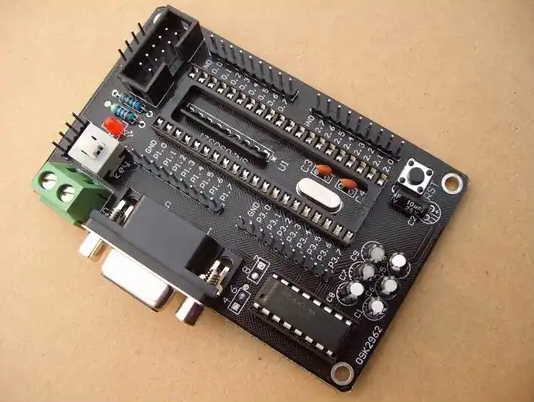
A functional minimum system strips away all application-specific components (like sensors, displays, or communication modules) to reveal the non-negotiable support circuits the MCU needs to operate. Think of it as the life support system for the chip’s brain.
1. Power Supply Circuit: The Lifeblood of Operation
The power supply is the most critical part of the minimum system. An unstable or noisy power source is the root cause of a majority of erratic MCU behaviors.
-
Voltage Regulation: Most MCUs (like popular ARM Cortex-M or AVR chips) require a clean, stable, low-voltage DC supply, typically 3.3V or 5V. The system picture must include a voltage regulator circuit (e.g., an LDO - Low Dropout Regulator) that steps down from a higher input voltage (like 9V from a battery or USB’s 5V). Choosing the correct regulator with adequate current rating and proper decoupling is non-negotiable for stability.
-
Power Decoupling and Filtering: This is where many novice designs falter. The MCU Minimum System Picture must clearly show an array of capacitors placed strategically across the power pins. Bulk capacitors (e.g., 10µF) handle larger current surges, while smaller ceramic capacitors (0.1µF or 100nF) are placed as close as possible to each power pin to filter high-frequency noise. These capacitors act as tiny local energy reservoirs, smoothing out voltage dips when the MCU’s internal circuits switch rapidly.
-
Clear Power Rails: A good schematic will visually distinguish between different voltage rails (e.g., 5V input, 3.3V core, 1.8V for analog sections) and ground nets. This clarity in the “picture” is crucial for both design and debugging.
2. Clock Circuit: The Heartbeat of Synchronization
The clock signal dictates the pace at which the MCU fetches and executes instructions. The minimum system must provide a precise and reliable timing reference.
-
Clock Sources: The system picture typically includes one of two options:
- External Crystal Oscillator: For applications requiring high timing accuracy (like UART communication, USB, or real-time operations), a crystal (e.g., 8MHz, 16MHz) with two load capacitors is connected to the MCU’s OSC_IN and OSC_OUT pins. The selection of crystal frequency and load capacitor values must match the MCU’s datasheet specifications precisely.
- Internal RC Oscillator: Many modern MCUs have built-in internal oscillators. While convenient and saving board space, they are generally less accurate. The system picture should indicate whether the internal or external source is being used, as this affects firmware configuration.
-
Clock Circuit Layout: The schematic must show the crystal placed extremely close to the MCU pins, with short and symmetric traces to minimize interference and ensure reliable startup. This part of the picture highlights best practices in PCB layout from the very beginning.
3. Reset and Boot Configuration Circuit: The Control for Startup
This circuit determines the MCU’s initial state and mode when power is applied.
-
Reset Circuit: It ensures the MCU starts in a known, predictable state. The simplest form is a resistor-capacitor (RC) network connected to the active-low reset pin (
/RSTorNRST). When power is applied, the capacitor charges slowly through the resistor, holding the pin low for a brief period before going high, allowing power and clocks to stabilize before execution begins. More robust designs may include a dedicated reset management IC (a supervisor). -
Boot Mode Selection: Most MCUs have specific pins (e.g.,
BOOT0,BOOT1) that are sampled at reset to decide where to fetch the first instruction from—internal Flash memory, system memory (for bootloaders), or external memory. The system picture must clearly show how these pins are pulled high or low via resistors to set the desired boot mode. An incorrect configuration here can render the MCU unprogrammable.
Why Visualizing the Complete “Picture” is Crucial
Having a clear, accurate MCU Minimum System Picture is more than an academic exercise; it is a practical necessity for success.
- Design Reliability: It serves as a checklist against which every new design can be verified before moving to PCB layout. Missing a decoupling capacitor or miswiring the boot pins can lead to costly board revisions.
- Efficient Troubleshooting: When a newly assembled board fails to respond (“bricked”), an engineer instinctively refers back to this picture. They will probe voltages on each power rail, check clock signal integrity with an oscilloscope, and verify reset pin behavior—systematically testing each pillar of the minimum system.
- Foundation for Expansion: This picture is the stable core onto which all application circuitry—GPIO peripherals, ADC sensor inputs, communication buses (I2C, SPI), and more—is attached. A weak core leads to a fragile overall system.
- Educational Tool: For learners, it provides a tangible, visual map of abstract concepts like decoupling, reset sequencing, and clock generation.
For those seeking high-quality reference designs, detailed schematics, and practical insights into building robust minimum systems for various MCU families (from STM32 and GD32 to ESP32 and beyond), platforms like ICGOODFIND can be an invaluable resource. They aggregate and curate technical documentation and design files from multiple sources, helping engineers find reliable reference “pictures” quickly.
Conclusion
The journey of creating any embedded device begins with a single, correct step: designing a reliable MCU Minimum System. The MCU Minimum System Picture encapsulates this foundational knowledge—the harmonious integration of clean power, a steady clock, and a controlled reset. It is the universal language of embedded hardware engineers. By meticulously crafting and understanding this essential circuit diagram, you lay an unshakable foundation upon which innovation can be built with confidence. Whether you are designing a complex industrial controller or a simple smart device, always start with a perfect minimum system picture; it is your most critical blueprint for success.