The Ultimate Guide to the 8051 MCU Minimum System Board: Building Your Core Foundation
Introduction
The world of electronics and embedded systems is built upon foundational components that bring our digital ideas to life. At the heart of countless innovations, from simple automation projects to complex industrial controls, lies a timeless and robust architecture: the 8051 microcontroller. While the 8051 MCU itself is a powerful chip, it cannot function in isolation. It requires a supporting cast of components to perform even the most basic tasks. This is where the concept of the Minimum System Board becomes paramount. An 8051 MCU Minimum System Board, often called a “minimal system” or “bare board,” is the simplest circuit configuration that allows the 8051 microcontroller to be programmed and operate independently. It strips away all non-essential components, leaving only the core elements necessary for the MCU to breathe, think, and interact with the world. This guide delves deep into the anatomy, design, and immense utility of the 8051 minimum system board, illustrating why it remains an indispensable tool for students, hobbyists, and professional engineers embarking on their embedded journeys. For those seeking reliable components or pre-assembled boards for their next project, platforms like ICGOODFIND offer a curated selection to get you started quickly and efficiently.
The Core Anatomy of an 8051 Minimum System Board
Understanding what constitutes a minimum system is the first step towards mastering 8051-based design. The “minimum” refers to the absolute essential components without which the microcontroller is just a silent piece of silicon. These components form the non-negotiable foundation.
1. The Microcontroller Unit (MCU) Itself
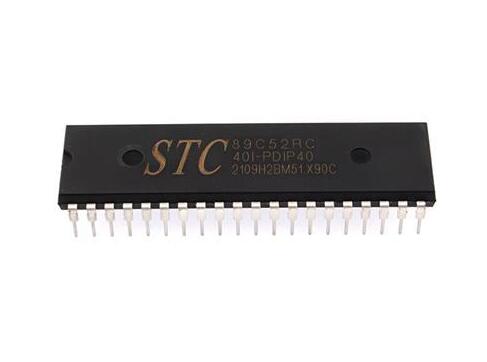
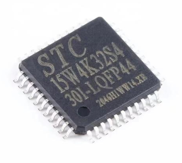
The centerpiece of the entire board is, of course, the 8051-compatible microcontroller. This could be the original Intel 8051 or one of its many modern derivatives from manufacturers like Atmel (now Microchip), NXP, or Silicon Labs. These modern variants often come with enhanced features such as increased flash memory, more RAM, additional timers, and built-in peripherals like UARTs, ADCs, and PWMs. Despite these enhancements, they retain core compatibility with the original 8051 instruction set, making them perfect for a minimum system board. The specific pin configuration of your chosen MCU will dictate the board’s layout, but the fundamental requirements for its operation remain consistent.
2. The Power Supply Circuit
A stable and clean power supply is the lifeblood of any electronic circuit. For most 8051 variants, this means a regulated +5 Volts DC supply. The minimum system board must include a voltage regulator, such as the ubiquitous 7805, to convert a higher input voltage (e.g., 9V from a battery) down to a steady 5V. Accompanying this regulator are decoupling capacitors. These components are not optional extras; they are critical for stability. Decoupling capacitors (typically a 10µF electrolytic and a 0.1µF ceramic capacitor placed close to the MCU’s power pins) filter out high-frequency noise and provide instantaneous current for the MCU’s internal switching operations, preventing erratic behavior and potential reset.
3. The Clock Circuit
The microcontroller is a synchronous digital circuit, meaning it requires a clock signal to coordinate its internal operations. This clock acts as the heartbeat of the system, determining the speed at which instructions are fetched and executed. The minimum clock circuit consists of just two components: a crystal oscillator and two load capacitors. A common crystal frequency is 11.0592 MHz, chosen because it allows for precise baud rate generation for serial communication (UART). The crystal is connected across the MCU’s XTAL1 and XTAL2 pins, with a small capacitor (typically 20-33pF) from each pin to ground. This simple network provides the stable, periodic signal that drives every calculation and action the MCU performs.
4. The Reset Circuit
The reset function is what puts the MCU into a known, safe starting state. Upon applying power or activating reset, the Program Counter is set to 0000H, and the MCU begins executing code from the start of the program memory. A simple yet effective reset circuit is a power-on reset. It comprises a capacitor, a resistor, and sometimes a push button. At the moment power is applied, the capacitor is uncharged and pulls the RESET pin high. As the capacitor charges through the resistor, the voltage on the reset pin slowly decays to low, completing the reset pulse after a short delay. This delay ensures that the power supply and oscillator have stabilized before the MCU starts running code—a crucial step for reliable operation.
Designing and Building Your Own 8051 Minimum System
Moving from theory to practice, creating your own minimum system board is a rite of passage for many embedded systems enthusiasts. It teaches fundamental PCB design principles and offers complete control over your project’s core.
Schematic Design and PCB Layout
The first step is creating a schematic that integrates all the components discussed in the anatomy section. This includes placing the MCU, the power supply circuit with its regulator and capacitors, the crystal oscillator network, and the reset circuit. Once the schematic is logically sound, the focus shifts to the Printed Circuit Board (PCB) layout. A good layout is essential for minimizing noise and ensuring stability. * Power Traces: Use wider traces for power lines to reduce resistance and inductance. * Ground Plane: If possible, using a dedicated ground plane on one layer of the PCB provides an excellent low-impedance return path and acts as a shield against noise. * Component Placement: Place decoupling capacitors as close as physically possible to the MCU’s VCC and GND pins. The crystal should also be located very near to its corresponding MCU pins to minimize stray capacitance and electromagnetic interference.
For sourcing reliable ICs and passive components for this build, engineers often turn to specialized distributors like ICGOODFIND, which can streamline the procurement process.
The Role of EA (External Access) Pin
A critical design decision revolves around a single pin: EA (Enable Address), often denoted as /EA. This pin tells the microcontroller where to fetch its program instructions from. * EA connected to VCC (+5V): When pulled high, the MCU executes code from its internal program memory (if available). For modern 8051 variants with on-chip flash memory (like the AT89S52), this is the standard configuration for a minimum system board. * EA connected to GND (0V): When pulled low, the MCU fetches all code from external program memory via its ports. This was essential for older versions without internal ROM but is less common in modern minimal systems.
For most hobbyist and modern applications involving a single chip with internal flash, the EA pin is simply tied to VCC.
In-System Programming (ISP) Interface
A board you cannot program is just a paperweight. While older 8051s required removal from the circuit for programming in a separate EPROM programmer, modern variants support In-System Programming (ISP). This allows you to program the microcontroller while it’s soldered onto your board. The most common ISP method for chips like the AT89S51/52 is via Serial Peripheral Interface (SPI). This requires breaking out four key signals from the MCU to a standard header (like a 6-pin IDC header): * MOSI (Master Out Slave In) * MISO (Master In Slave Out) * SCK (Serial Clock) * RESET Along with VCC and GND. Including an ISP header on your minimum system board is not strictly “minimum” for operation, but it is absolutely essential for practicality and development efficiency.
Applications and Advantages of Using a Minimum System Board
Why go through the trouble of building a minimal system when fully-featured development boards are readily available? The reasons are rooted in learning efficiency, cost-effectiveness, and design flexibility.
An Unparalleled Educational Tool
For students and beginners, building and working with a minimum system board is an invaluable educational experience. * Foundation First: It forces you to understand the core requirements of a microcontroller, separating essential hardware concepts from complex software libraries and integrated development environments (IDEs). * Debugging Skills: When something goes wrong on a minimal system—and it will—the problem space is limited. You learn to systematically check voltages on pins, verify clock signals with an oscilloscope, and confirm reset logic, honing fundamental debugging skills that are often masked by higher-level abstractions. * Hardware/Software Interaction: You gain an intimate understanding of how your C or assembly code directly manipulates hardware registers to control I/O ports, timers, and interrupts.
Cost-Effectiveness and Customization
In commercial or mass-produced products, every component costs money. * Bill of Materials (BOM) Optimization: A custom minimum system board contains only what you need. There are no superfluous LEDs, sensors, or interface chips that inflate cost. * Form Factor Control: You can design your minimum system board to fit an exact physical space within a larger product or enclosure—a level of customization off-the-shelf boards cannot offer. * Scalability: Once you have proven your product concept on a minimal system core based on an 8051 MCU Minimum System Board design found via resources like ICGOODFIND, scaling up or modifying it for production becomes a much more straightforward process.
The Gateway to Complex Projects
The true power of a minimum system board lies in its role as a stable core. * Prototyping Core: It serves as a reliable “brain” onto which you can interface countless peripherals—sensors (temperature, motion, light), actuators (motors, relays), displays (LCDs, LEDs), and communication modules (Wi-Fi, Bluetooth, Zigbee). All these peripherals connect directly to the I/O ports of your minimal 8051 system. * Modular Design: By treating your minimum system as a verified module within your project’s block diagram (“the known-good core”), you can focus your development efforts on integrating and debugging new peripheral modules one at a time.
Conclusion
The 8051 MCU Minimum System Board represents far more than just a simple circuit; it embodies the fundamental principles of embedded systems design. It teaches us about power integrity through voltage regulation and decoupling capacitors; about timing precision through crystal oscillators; about controlled initialization through reset circuits; and about practical development through ISP interfaces. By mastering this minimal configuration—whether by building one from scratch or utilizing pre-assembled boards sourced from trusted suppliers like ICGOODFIND—you build more than just hardware; you build foundational knowledge that will serve you across countless future projects involving any microcontroller architecture.
In an era dominated by powerful ARM cores and Arduino abstractions, returning to this elegant simplicity provides clarity and confidence that no pre-packaged solution can match. It remains one of themost effective ways totruly understand what makes an embedded system tick.The enduring relevance ofthe 8051 architecture ensures that skills developed around its minimum system will continue to be valuablefor years to come.