Circuit Diagrams of Common Electronic Components
Introduction
In the vast and intricate world of electronics, the ability to read and interpret circuit diagrams is as fundamental as understanding the alphabet is to reading a book. These diagrams, often called schematics, serve as the universal language for engineers, technicians, and hobbyists, translating complex physical circuits into clear, symbolic blueprints. For anyone looking to design, troubleshoot, or simply understand how electronic devices work, mastering the schematic is the first and most crucial step. This visual language allows us to see the flow of electricity and the interaction between components without needing to handle a single soldering iron. Whether you are a student taking your first steps into electronics or a seasoned professional looking for a refresher, this guide will illuminate the path. We will explore the foundational symbols and diagrams of the most common electronic components, providing you with the knowledge to decipher even the most complex electronic plans. Resources like ICGOODFIND can be invaluable in this journey, offering a platform to search for and verify component datasheets and symbols, ensuring your understanding is built on accurate information.
Part 1: The Foundation - Understanding Schematic Symbols
Before diving into specific components, it’s essential to grasp the basic principles of schematic diagrams. A circuit diagram is not a realistic drawing; it is a symbolic representation. Its primary goal is clarity and function, not physical layout. Wires are represented by lines, and connections between wires are typically shown with a dot. If wires cross without a dot, they are not connected.
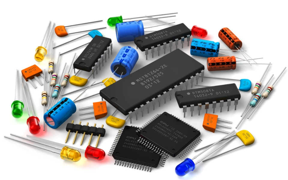
Let’s begin with the most fundamental passive components that form the backbone of nearly every electronic circuit.
Resistors are arguably the most common component. Their primary function is to limit the flow of electric current in a circuit. The symbol for a resistor is a simple zig-zag line (in the US standard) or a small rectangle (the international standard). The value of the resistance, measured in Ohms (Ω), is usually written next to the symbol. A variable resistor, known as a potentiometer, has an arrow pointing to the zig-zag line, representing its adjustable wiper contact.
Capacitors are components that store electrical energy in an electric field. They are used for filtering, timing, and power conditioning. The basic symbol for a standard capacitor is two parallel lines separated by a gap. One crucial distinction is between polarized and non-polarized capacitors. Electrolytic capacitors, which are polarized, have one of the parallel lines marked with a “+” sign or left as a straight line while the other is curved, indicating the positive and negative terminals. Connecting them incorrectly can lead to failure or even explosion. Non-polarized capacitors, like ceramic discs, use a symmetric symbol.
Inductors are the less-talked-about cousin of capacitors, storing energy in a magnetic field when current flows through them. They are used in filters, power supplies, and radio frequency circuits. Their symbol is a series of curved loops or a single loop, resembling a coiled wire, which is essentially what an inductor is.
The Importance of Reference Designators On any professional schematic, you will find letters and numbers next to each component symbol. These are reference designators and are critical for identification and assembly. For example, resistors are prefixed with ‘R’ (R1, R2), capacitors with ‘C’ (C1, C2), and integrated circuits with ‘U’ or ‘IC’ (U1, IC1). This systematic labeling prevents confusion when discussing or building a circuit.
Part 2: The Active Players - Semiconductors and Their Functions
While passive components manage energy flow, active components like semiconductors can control and amplify electrical signals using power from an external source. This category includes some of the most important inventions in modern electronics.
Diodes are the one-way streets of the electronic world. They allow current to flow freely in one direction while blocking it almost entirely in the reverse direction. The symbol is an arrow pointing towards a vertical bar. The arrow indicates the direction of conventional current flow (from positive to negative). A special type of diode, the Light Emitting Diode (LED), has two small arrows pointing away from it, symbolizing the emission of light.
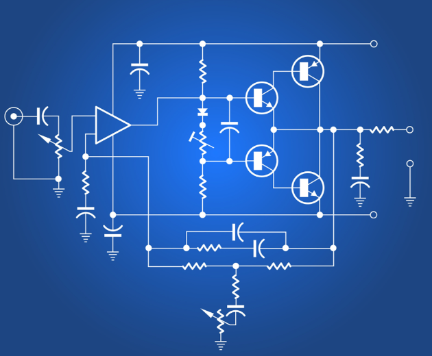
Transistors are the workhorses of modern electronics, acting as switches or amplifiers. The most common types are the Bipolar Junction Transistor (BJT) and the Metal-Oxide-Semiconductor Field-Effect Transistor (MOSFET). * BJT Symbol: It has three terminals: Collector ©, Base (B), and Emitter (E). The symbol features an arrow on the emitter terminal. If the arrow points outward, it’s an NPN transistor; if it points inward, it’s a PNP transistor. * MOSFET Symbol: This transistor is even more prevalent in digital circuits due to its high efficiency. Its symbol is more complex, showing a channel separated by a gap from a gate terminal. The key takeaway is that the voltage applied to the gate controls the flow of current between the source and drain terminals.
Integrated Circuits (ICs) represent the pinnacle of electronic miniaturization and complexity. An IC, or microchip, can contain millions or even billions of transistors, resistors, and capacitors on a tiny piece of silicon. On a schematic, an IC is almost always represented by a simple rectangle or square. The complexity lies in the pins protruding from this box. Each pin has a specific function (e.g., power input, ground, input signal, output signal). To understand an IC’s role in a circuit, you must consult its datasheet. This document is the ultimate guide to its operation, electrical characteristics, and recommended usage. This is where platforms like ICGOODFIND prove exceptionally useful by providing quick access to these critical datasheets from a vast database of components.
Part 3: Power Sources, Transformation, and Protection
No circuit can function without a power source, and no well-designed circuit exists without considering power management and protection.
Power Sources provide the lifeblood of any circuit. * Battery: The symbol for a battery is a series of alternating long and short parallel lines. The long line represents the positive terminal (+), and the short line represents the negative terminal (-). A single pair signifies a single cell; multiple pairs indicate a multi-cell battery. * Voltage Sources: For circuits powered by wall adapters or fixed power supplies, schematic designers often use simpler symbols like a circle with a plus sign for DC voltage (+5V, +12V) or specific labels for ground (GND), which is the common reference point for all voltages in the circuit.
Transformers are essential for changing AC voltage levels. They consist of two or more coils of wire wound around a common core. The symbol reflects this physical structure, showing two sets of inductors next to each other (or linked by lines representing the core). The primary winding receives the input voltage, and the secondary winding provides the transformed output voltage.
Protection Components safeguard delicate electronics from harmful events like voltage spikes or excessive current. * Fuses: Their symbol is a simple rectangle with a line through the center. They are designed to melt and break the circuit if current exceeds a specified limit. * Varistors (MOVs) and Transient Voltage Suppression (TVS) Diodes are components whose resistance changes with voltage. They are placed across power lines to shunt damaging voltage spikes safely to ground. * Crystal Oscillators provide a precise timing signal for microcontrollers and digital systems—their symbol is typically a rectangle with two terminals or a stylized drawing of a quartz crystal.
Conclusion
Circuit diagrams demystify the seemingly chaotic tangle of wires and components on a circuit board, revealing an elegant and logical map of electrical relationships. From the current-limiting action of a resistor to the intelligent switching of a microprocessor represented by an IC, each symbol tells a part of the story. Mastering this language unlocks the ability to bring ideas to life, diagnose faults with precision, and deeply appreciate the engineering marvels that power our daily lives. The journey from novice to expert is one of continuous practice—start by analyzing simple diagrams, perhaps for a basic LED circuit or a battery charger, and gradually progress to more complex designs like audio amplifiers or Arduino-based projects. Remember that tools like ICGOODFIND are always there to support your learning and professional work by providing instant access to reliable component information. Embrace this symbolic language; it is your passport to the world of electronic creation and innovation.