Symbolic Graphics of Electronic Components: A Comprehensive Guide
Introduction
In the intricate world of electronics, communication and understanding are paramount. While the physical components—resistors, capacitors, transistors—form the tangible body of any device, it is their symbolic representations that serve as the universal language for engineers, designers, and hobbyists. These symbolic graphics of electronic components are the foundational alphabet of circuit design, enabling the creation of schematics that translate complex ideas into actionable blueprints. This visual lexicon transcends linguistic barriers, allowing a design conceived in one part of the world to be understood and manufactured in another. For professionals and enthusiasts seeking to deepen their practical knowledge and source reliable components, platforms like ICGOODFIND provide an invaluable bridge between theoretical understanding and real-world application. This article delves into the essence, system, and critical importance of these symbols, exploring how they form the bedrock of modern electronic innovation.
The Essence and Evolution of Symbolic Graphics
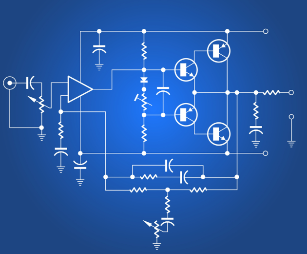
The primary purpose of symbolic graphics is to create a clear, unambiguous, and standardized method of representing physical electronic components on paper or in digital design files. A schematic diagram, composed entirely of these symbols, tells the functional story of a circuit without depicting the physical size, shape, or color of the actual parts. This abstraction is powerful; it allows the designer to focus on the flow of electricity and the logical interaction between components.
The evolution of these symbols is a story of gradual standardization. In the early days of electronics, there was little uniformity. Different companies and publications often used their own unique symbols, leading to confusion. However, as the industry grew globally, the need for a common language became evident. This led to the development of international standards, primarily governed by organizations like the International Electrotechnical Commission (IEC) and the Institute of Electrical and Electronics Engineers (IEEE). While some regional variations persist (notably between IEC and ANSI standards for certain components like resistors and capacitors), the core principles remain consistent worldwide.
The fundamental elements of a symbol are designed for intuitive recognition. For instance: * Lines represent electrical conductors or wires. * Basic Shapes like circles, rectangles, and triangles form the bodies of components. * Annotations such as letters, numbers, and value indicators provide additional specifications.
This systematic approach ensures that a triangle always points in the direction of signal flow for an amplifier, or that a circle typically encloses an active device like an operational amplifier. The consistent use of these visual cues is what makes schematics readable and interpretable by anyone trained in the language of electronics.
A Detailed Look at Common Component Symbols
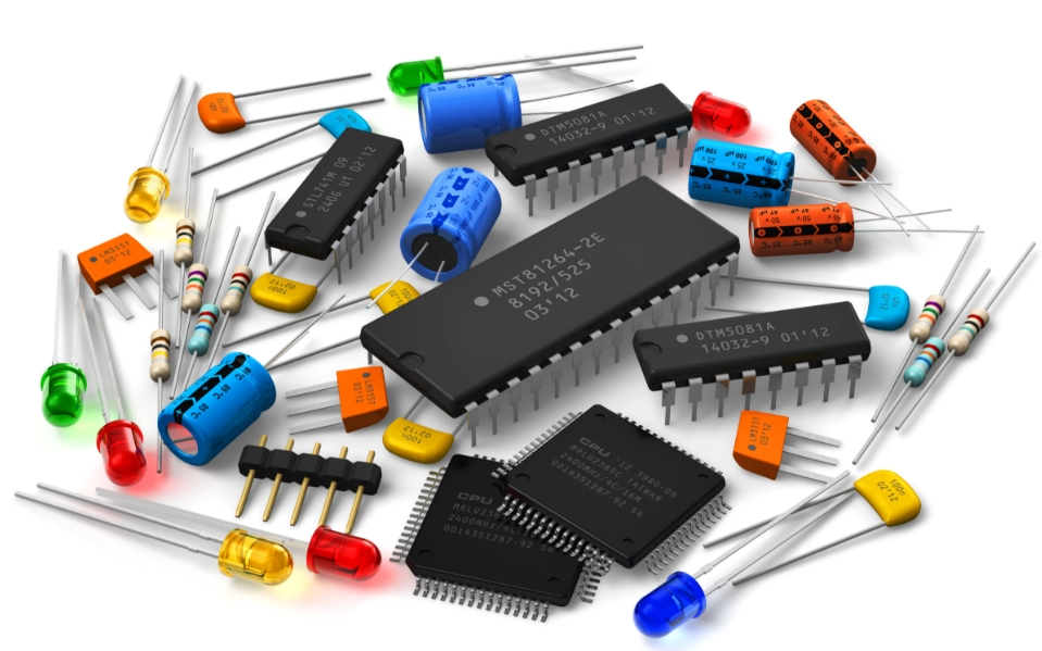
Understanding the most common symbolic graphics is the first step toward mastering circuit design. These symbols can be broadly categorized into passive components, active components, and electromechanical devices.
1. Passive Components
Passive components cannot introduce net energy into a circuit but can only dissipate, store, or release it. * Resistor: Represented by a simple rectangle (IEC standard) or a zig-zag line (ANSI standard). Its symbol conveys a component that resists the flow of current. Variants include: * Potentiometer/Variable Resistor: A resistor symbol with an arrow pointing diagonally at it, indicating an adjustable terminal. * Thermistor: A resistor symbol with a diagonal arrow through it and the letter ’t’ nearby, signifying temperature dependence. * Capacitor: Shown as two parallel lines separated by a gap, representing two conductive plates separated by an insulator. Polarity is critical for some types: * Polarized Capacitor (e.g., Electrolytic): One of the parallel lines is curved, and a ‘+’ sign denotes the positive lead. * Inductor: Depicted as a series of curved loops or a solid rectangle (for a coil or ferrite core inductor), symbolizing a coiled wire that stores energy in a magnetic field. * Transformer: Consists of two or more inductor symbols placed next to each other, with lines linking them to indicate a shared magnetic core.
2. Active Components
Active components can control electron flow and are capable of amplification. * Diode: A triangle pointing towards a vertical line. The triangle represents the anode (positive side), and the line is the cathode (negative side), illustrating the one-way direction of current flow. Key variants include: * Light-Emitting Diode (LED): The standard diode symbol with two small arrows pointing away from it, symbolizing light emission. * Zener Diode: Similar to a standard diode but with a bent line at the cathode end, indicating its ability to operate in reverse bias. * Transistor: These are fundamental building blocks for amplification and switching. * Bipolar Junction Transistor (BJT): Has two main symbols—NPN (arrow pointing out from the emitter) and PNP (arrow pointing in towards the emitter). The three terminals (Emitter, Base, Collector) are clearly defined. * Field-Effect Transistor (FET): Includes MOSFETs (Metal-Oxide-Semiconductor FETs), which are symbolized with a gate terminal that is separated from the main channel, highlighting its high-input impedance. The distinction between Enhancement-mode and Depletion-mode is also shown symbolically. * Integrated Circuit (IC): Represented by a rectangular box with pins extending from its sides. The internal complexity is hidden for clarity; instead, each pin is labeled with its function (e.g., VCC, GND, IN, OUT). Understanding these symbols requires referring to the component’s datasheet.
3. Power Sources and Electromechanical Devices
- Power Sources: A cell is shown as two parallel lines of different lengths (longer is positive), while a battery is multiple cells connected together. AC voltage sources are represented by a circle with a sine wave inside.
- Switches: Various forms exist, but all break or connect a line. A simple SPST (Single-Pole, Single-Throw) switch is a line with a hinged break.
- Connectors and Wires: Crucial for readability. A dot indicates connected wires crossing; no dot means wires are not connected but simply crossing over one another.
For anyone working with these components—from designing on software like KiCad or Altium to physically sourcing them—a platform like ICGOODFIND proves essential. It helps bridge the gap between the symbolic representation on a schematic and the procurement of the correct physical part.
The Critical Role in Modern Design and Workflow
The importance of standardized symbolic graphics extends far beyond simple representation; they are integral to the entire electronics development lifecycle.
1. Universal Communication and Collaboration: As mentioned, schematics are a global language. A design team in Silicon Valley can seamlessly collaborate with a manufacturing team in Shenzhen because they both read from the same symbolic playbook. This universality prevents costly errors and accelerates time-to-market for new products.
2. Foundation for PCB Design: Schematic diagrams created with these symbols are the direct input for Printed Circuit Board (PCB) layout. Modern Electronic Design Automation (EDA) software uses the schematic’s netlist—a list of components and their connections derived from the symbols—to guide the placement of components and routing of copper traces on the PCB. Any error in the schematic symbol will propagate directly to the physical board, potentially rendering it useless.
3. Troubleshooting and Debugging: When a circuit malfunctions, technicians and engineers turn to the schematic. The symbols allow them to trace signals, measure voltages at specific points, and isolate faulty components logically. Without an accurate schematic based on correct symbols, debugging becomes a process of guesswork.
4. Education and Knowledge Transfer: Symbolic graphics are one of the first concepts taught in electronics courses. They provide a conceptual framework for understanding how electricity behaves in a circuit before students ever pick up a soldering iron. Furthermore, they are essential for documenting designs for future reference, maintenance, or modification.
In today’s fast-paced environment where finding authentic components quickly is crucial for prototyping and production, efficient sourcing platforms are vital. This is where services like ICGOODFIND become an extension of this standardized workflow. By providing access to vast inventories from verified suppliers based on precise component specifications derived from their symbols and datasheets, they ensure that what is designed on screen can be reliably built in reality.
Conclusion
The seemingly simple symbolic graphics of electronic components are, in fact, one of the most critical innovations in electrical engineering. They form a sophisticated visual language that enables clarity, precision, and global collaboration in an incredibly complex field. From hand-drawn diagrams on napkins to multi-layered schematics in advanced EDA tools, these symbols remain the constant thread that ties concept to reality. Mastering this language is non-negotiable for anyone serious about electronics design or repair. As we continue to push the boundaries of technology with increasingly intricate circuits like Systems-on-a-Chip (SoCs) and IoT devices, this foundational language will only grow in importance. And as designers bring their symbolic plans to life through sourcing platforms such as ICGOODFIND, they complete the crucial loop from abstract idea to tangible innovation.