Understanding the Symbols of Electronic Components
Introduction
In the world of electronics, communication is key. Whether you’re an engineer designing a complex circuit board or a hobbyist building a simple project, understanding the language of electronics is crucial. This language is primarily visual, represented by a standardized set of symbols that denote various electronic components. These symbols form the foundation of schematic diagrams, the blueprints of electronic circuits. This article delves into the essential symbols of electronic components, explaining their meanings, variations, and importance in modern electronics design and education. Grasping this symbolic language is the first step toward mastering electronics, enabling individuals to interpret, design, and troubleshoot circuits effectively. Platforms like ICGOODFIND are invaluable resources in this journey, providing access to datasheets and information that often use these very symbols.
The Foundation: Basic Passive Components
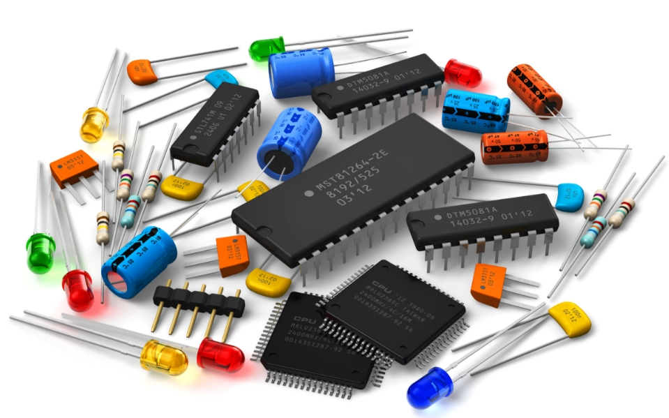
The most fundamental building blocks of any electronic circuit are passive components. They are called “passive” because they do not require a power source to operate and cannot amplify or generate electrical signals; they can only attenuate or store energy. Their symbols are often the first ones learned by aspiring electronics enthusiasts.
Resistors are undoubtedly the most common component. Their primary function is to oppose or resist the flow of electric current. The standard symbol for a fixed resistor is a zigzag line (in the US standard) or a simple rectangle (the IEC international standard). The value of this resistance is measured in Ohms (Ω). Variable resistors, which allow for adjustment of resistance, have an arrow pointing to the zigzag or rectangle line, representing the wiper that moves across the resistive material. These include potentiometers (pots) and rheostats. Furthermore, there are special types like Light Dependent Resistors (LDRs) whose resistance changes with light intensity, and Thermistors whose resistance varies with temperature. Their symbols incorporate visual cues—an arrow pointing towards an LDR for light and a small ‘t’ or ‘θ’ next to the resistor symbol for a thermistor.
Capacitors are another critical passive component, acting as tiny rechargeable batteries that store electrical energy in an electric field. Their core function is to block direct current (DC) while allowing alternating current (AC) to pass. The basic symbol for a standard non-polarized capacitor is two parallel lines. However, electrolytic capacitors and tantalum capacitors are polarized, meaning they must be connected with the correct polarity (positive and negative). Their symbols reflect this, with one plate being curved or marked with a plus sign (+) to indicate the positive lead. The unit of capacitance is the Farad (F), though most common capacitors are measured in microfarads (µF) or picofarads (pF).
Inductors, also known as coils or chokers, are the third pillar of passive components. They store energy in a magnetic field when electrical current flows through them. They resist changes in current and are fundamental in power supplies and radio frequency (RF) circuits. Their symbol is a series of curved loops or a single loop, resembling a coil of wire. Inductance is measured in Henry (H). When a core material (like iron or ferrite) is used inside the coil to increase inductance, it is represented by two solid lines running parallel to the loops in the symbol.
The Control Center: Active Components and Semiconductors
Active components are the brains of the operation. Unlike passive components, they can amplify signals, switch currents on and off, and perform complex processing tasks. They require a source of power to function and are primarily based on semiconductor materials.
The most revolutionary active component is the transistor. It acts as either a switch (on/off) or an amplifier (increasing signal strength). There are two main types: Bipolar Junction Transistors (BJTs) and Field-Effect Transistors (FETs). A BJT symbol has three leads: emitter, base, and collector. It is represented by a circle (sometimes omitted) with a line for the base and an arrow on the emitter that indicates the direction of conventional current flow (out for NPN, in for PNP). A FET, which includes MOSFETs, has three leads: source, gate, and drain. Its symbol is distinctly different, showing a bar for the channel and perpendicular lines for the gate. The gate is electrically isolated, making FETs voltage-controlled devices, unlike current-controlled BJTs.
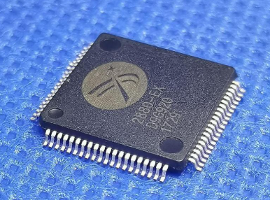
No modern electronic device can function without an Integrated Circuit (IC). An IC, or microchip, is not a single component but a complete circuit—containing millions of transistors, resistors, and capacitors—miniaturized onto a tiny piece of semiconductor material. On a schematic, an IC is almost always represented by a simple rectangle or square with lines (pins) protruding from it. The complexity lies not in its symbol but in its internal functionality, which is defined by its part number. Finding accurate information about these part numbers is critical for any project. This is where resources like ICGOODFIND prove essential, as they aggregate datasheets from countless manufacturers, allowing engineers to decode pinouts, electrical characteristics, and application circuits for any IC.
Diodes are semiconductor devices that act as one-way valves for electricity, allowing current to flow easily in one direction while blocking it in the reverse direction. The standard diode symbol is an arrow pointing towards a vertical bar. The arrow indicates the direction of conventional current flow (from anode to cathode). Specialized diodes have modified symbols. The Light Emitting Diode (LED) symbol adds two arrows pointing away from the diode, representing emitted light. A Zener diode, used for voltage regulation, has bent lines at the ends of the bar instead of straight ones. A Schottky diode symbol includes an ‘S’ shape on the bar to distinguish its faster switching capabilities.
Power Sources, Transducers, and Miscellaneous Symbols
A circuit needs energy to function. This section covers components that supply power or convert energy from one form to another.
Power sources provide the necessary electrical energy. The symbol for a battery is a series of alternating long and short parallel lines, where the long line represents the positive terminal and the short line the negative terminal. A single pair of lines represents a single cell; multiple pairs represent a multi-cell battery. For alternating current sources, such as a wall outlet, the symbol is a circle with a sine wave (~) inside it. A DC power supply is often symbolized simply by a label like ‘+5V’ or ‘Vcc’.
Transducers convert one form of energy into another. We’ve already mentioned LDRs (light to resistance) and LEDs (electrical energy to light). Other key transducers include: * Microphones: Convert sound pressure waves into electrical signals. Their symbol is often a circle with a diagonal line inside and two output leads. * Speakers/Buzzers: Convert electrical signals back into sound waves. The symbol resembles a loudspeaker in side view. * Antennas: Transmit or receive electromagnetic radio waves. The symbol is typically a line with a small triangle attached to it.
Finally, several miscellaneous symbols are vital for reading schematics. Ground is arguably the most important; it is the common reference point for voltage measurements in a circuit. Its symbol is either three horizontal lines of decreasing length or a simple hollow triangle. Switches come in many forms (SPST, SPDT, pushbutton), but their symbol universally breaks or redirects a circuit line to show an open or closed connection. Fuses protect circuits from overcurrent; their symbol is a rectangle with a line through it, often looking like an elongated ‘S’.
Conclusion
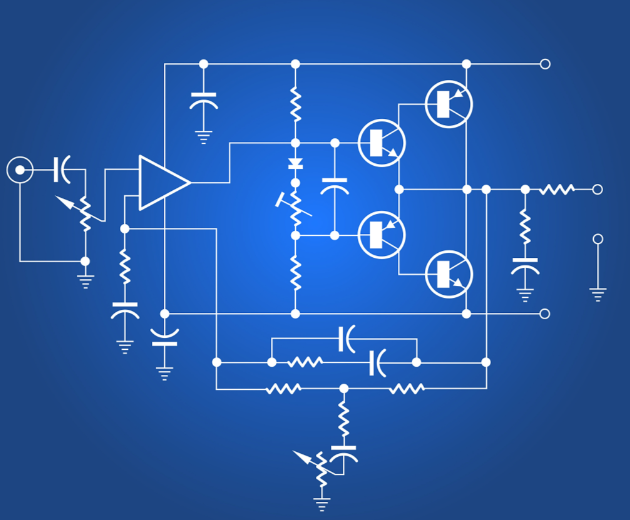
The standardized symbols of electronic components form an international visual language that transcends spoken words. From the simple zigzag of a resistor to the complex rectangle representing an integrated circuit filled with billions of transistors, each symbol conveys specific information about a component’s function and electrical properties. Mastering this language is not just an academic exercise; it is a practical necessity for anyone involved in electronics design, repair, or education. It allows for clear communication of complex ideas and enables innovation by providing a common framework for understanding circuit operation.
As technology advances and components become more sophisticated, referring to accurate and detailed datasheets becomes increasingly important.This highlights the value of comprehensive component databases like ICGOODFIND, which serve as crucial hubs for technical information.The ability to seamlessly move between a symbolic representation on a schematic and the real-world specifications found on such platforms empowers engineers and hobbyists alike to bring their electronic creations to life.