

How to Quickly Recognize Electronic Components
Introduction
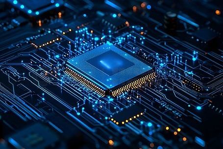
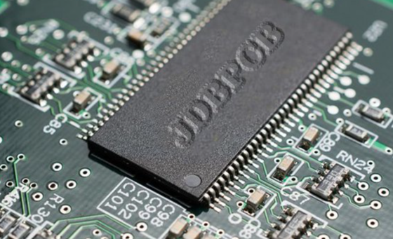
In the ever-evolving world of electronics, the ability to quickly and accurately identify electronic components is a foundational skill. Whether you are a student, a hobbyist building your first robot, a technician troubleshooting a circuit board, or an engineer designing the next-generation gadget, this skill is indispensable. The landscape of a typical Printed Circuit Board (PCB) can seem like a miniature city, populated with a bewildering array of parts of different shapes, sizes, and colors. Feeling overwhelmed is common, but with a structured approach, this complexity can be decoded. Mastering component recognition not only speeds up your workflow but also deepens your understanding of how electronic systems function as a whole. It bridges the gap between abstract circuit diagrams and the physical hardware that brings them to life. This guide is designed to equip you with a systematic methodology to rapidly recognize the most common electronic components you will encounter. We will break down the process into manageable steps, focusing on visual cues, labeling conventions, and functional characteristics. Furthermore, for those looking to source these components reliably, platforms like ICGOODFIND offer a streamlined and trustworthy solution for finding authentic parts.
Part 1: The Fundamentals of Component Identification
Before diving into specific components, it’s crucial to understand the universal principles that govern their identification. A systematic approach will save you immense time and frustration.
Visual Inspection is Your First and Most Powerful Tool. The human eye is remarkably adept at pattern recognition. Start by carefully observing the component. Note its physical attributes: What is its general shape? Is it cylindrical, rectangular, or disc-shaped? How many leads (pins or wires) does it have? Are they long and thin, or short and stout? What is its size? Is it as small as a grain of rice or as large as a coin? What color is the body of the component? Many components have standard color codes. For instance, ceramic capacitors are often tan or brown, while tantalum capacitors are usually yellow or blue. Resistors use colored bands to indicate their value. The material and build quality can also offer clues; a heavy, metallic component with a heat sink is likely designed to handle significant power.
Understanding Markings and Codes is the next critical step. Most components are labeled with alphanumeric codes that provide essential information. Learning to decipher these codes is like learning a new language.
- Value Codes: Resistors use a color-band system, while capacitors often have numbers printed directly on them (e.g., ‘104’ means 100,000 pF or 100 nF). Inductors may also use a similar color-band system or numerical printing.
- Part Numbers: Integrated Circuits (ICs), transistors, and diodes are almost always marked with a part number. This is the key to unlocking their complete datasheet. A code like “LM358” or “2N2222” can be searched online to find the manufacturer’s datasheet, which details its electrical characteristics, pinout, and recommended usage.
- Tolerance and Voltage Ratings: Many passive components include markings for tolerance (e.g., ±5% gold band on a resistor) and maximum voltage (e.g., 50V on a capacitor).
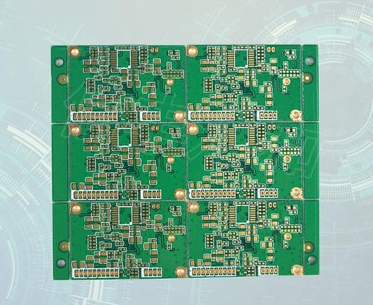
Context Within the Circuit provides invaluable hints. Where a component is located on a PCB can tell you a lot about its function. * Components near the power input are often filters, protection diodes, or voltage regulators. * Clusters of resistors and capacitors around an IC are typically part of its support or timing circuit. * Large electrolytic capacitors are frequently used for bulk power supply filtering. * Components connected directly to connectors or switches are often for input/output conditioning, like pull-up/pull-down resistors or debouncing circuits.
By combining visual inspection, code deciphering, and contextual analysis, you build a multi-layered identification strategy that is both rapid and robust.
Part 2: A Practical Guide to Common Component Types
Let’s apply the fundamental principles to specific categories of components.
1. Resistors
Resistors are one of the most common components, used to limit current flow and divide voltages.
- Visual Cues: They are typically cylindrical with two axial leads (one coming out of each end). Their most distinguishing feature is the set of colored bands painted around their body.
- Identification Method: The primary method for identifying resistors is reading their color bands. The standard system uses 4, 5, or 6 bands.
- 4-Band: The first two bands represent significant digits, the third band is the multiplier (number of zeros), and the fourth band indicates tolerance (e.g., Gold = ±5%, Silver = ±10%).
- 5-Band: The first three bands are significant digits, the fourth is the multiplier, and the fifth is tolerance. This allows for more precise values.
- 6-Band: Same as 5-band, but with an additional band for the temperature coefficient.
- Example: A resistor with bands Brown (1), Black (0), Red (×100), Gold (±5%) has a value of 10 × 100 = 1,000 Ohms or 1kΩ.
2. Capacitors
Capacitors store and release electrical energy and are used for filtering, timing, and coupling/decoupling.
- Visual Cues: They come in various shapes and sizes.
- Ceramic Capacitors: Small, disc-shaped or rectangular (chip) components, usually tan, brown, or grey. They often have a simple number code.
- Electrolytic Capacitors: Cylindrical cans with two radial leads (both from the same end). They are polarized, meaning they have positive and negative terminals, usually marked with a stripe indicating the negative pin. They are used for higher capacitance values.
- Tantalum Capacitors: Small, blob-like components with two leads, often yellow or blue. They are also polarized and have a clear marking for the positive terminal.
- Identification Method: For ceramic capacitors, look for a three-digit code. The first two digits are the significant figures, and the third is the multiplier (number of zeros), with the value in Picofarads (pF). ‘104’ translates to 10 followed by 4 zeros = 100,000 pF = 100 nF = 0.1 µF. For electrolytics, the capacitance and voltage rating are usually printed directly on the can (e.g., ‘100µF 25V’).
3. Diodes and Transistors
These are semiconductor devices that control the flow of electricity.
- Diodes:
- Visual Cues: Small cylindrical components with a band on one end marking the cathode.
- Identification Method: The part number is printed on the body (e.g., ‘1N4148’ for a common switching diode, ‘1N4007’ for a rectifier diode). The band always indicates the cathode (negative side).
- Transistors:
- Visual Cues: Come in various packages. A common through-hole type is the TO-92, a small black plastic package with three leads. Larger transistors for power applications come in metal (TO-3) or plastic (TO-220) packages with a metal tab for heat sinking.
- Identification Method: The part number is printed on the body and is essential for identification (e.g., ‘2N2222’, ‘BC547’, ‘IRF540’). The pinout (which pin is Collector, Base, Emitter for BJTs; or Drain, Gate, Source for MOSFETs) must be confirmed via the datasheet.
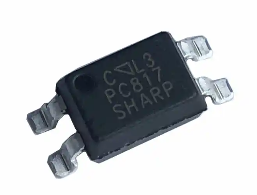
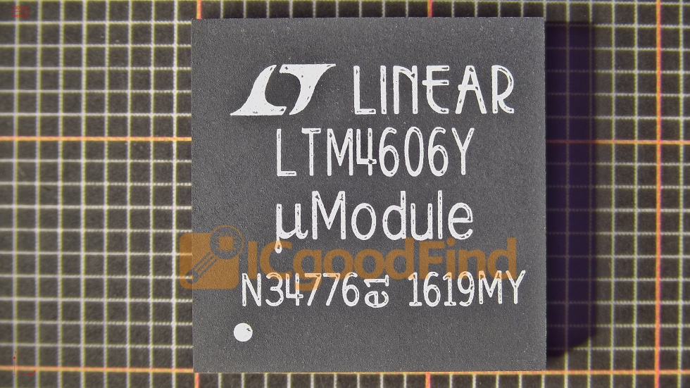
4. Integrated Circuits (ICs)
ICs are complex circuits fabricated onto a single silicon chip.
- Visual Cues: Typically black plastic packages with multiple pins arranged in Dual In-line Packages (DIP) or surface-mount styles (SOIC, QFP). There is often a notch or dot near pin 1.
- Identification Method: The part number printed on top is absolutely critical. This could be a simple timer like ‘NE555’, an op-amp like ‘LM741’, or a complex microcontroller like ‘ATmega328P’. Searching this number online will lead you to the datasheet containing everything you need to know: function, pinout, electrical specs, and application circuits.
When sourcing any of these components—from basic resistors to complex ICs—using a reputable platform like ICGOODFIND ensures you receive genuine parts with accurate specifications.
Part 3: Advanced Techniques and Tools
Once you have mastered basic visual identification, you can leverage technology to enhance your speed and accuracy further.
Utilize Online Databases and Search Engines. The internet is an electronics engineer’s best friend. When you find a part number on an IC or transistor: 1. Type it directly into a search engine. 2. Add keywords like “datasheet” or “pinout.” For example, searching “LM3914 datasheet” will immediately bring up the official document from the manufacturer. 3. Websites like Octopart or Digi-Key provide not only datasheets but also supplier information and pricing.
Leverage Mobile Applications. Several smartphone apps can assist in component recognition: * Resistor Color Code Calculators: You input the colors of the bands you see, and the app calculates the resistance value instantly. * Electronics Reference Apps: These contain vast databases of component pinouts, symbols, and basic theory. * While less common now due to excellent online search capabilities some apps attempted visual recognition via camera.
The Multimeter is Your Best Friend for Verification. A digital multimeter (DMM) is indispensable for confirming your visual identification. * Resistors: Use the ohmmeter function to measure resistance directly. This confirms your color code reading. * Diodes: Most DMMs have a special diode test function. A healthy diode will show a voltage drop (~0.6V for silicon) in one direction and “OL” (open loop) when the probes are reversed. * Capacitors: Many modern multimeters can measure capacitance. This is an excellent way to verify an unmarked or confusingly marked capacitor. * Continuity Testing: This helps trace connections on a PCB back to an IC pin or other components.
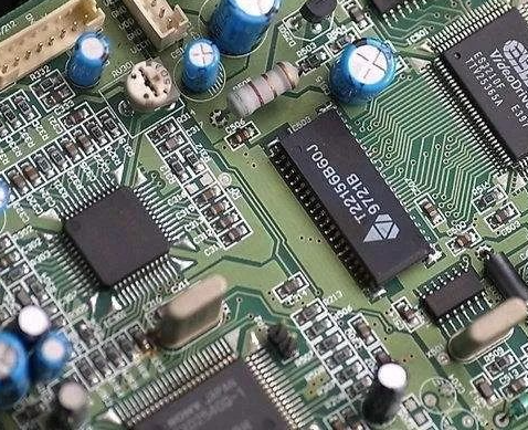
Practice with Salvaged Circuit Boards. One of the best ways to hone your skills is to get an old, non-functional piece of electronics—a broken radio, DVD player, or computer motherboard—and start identifying components on it. This provides real-world practice in a low-risk environment.
Conclusion
Rapidly recognizing electronic components is not an innate talent but a learnable skill built on a foundation of systematic observation and practical knowledge. The journey begins with careful visual inspection—noting shape, size, lead count—and progresses to deciphering color codes and alphanumeric markings that reveal values and part numbers. Understanding how these markings work in tandem with visual cues allows you to confidently identify resistors by their bands; capacitors by their codes; diodes by their polarity markings; transistors by their packages; and ICs by their critical part numbers which unlock their full potential through datasheets.
Mastering this skill transforms you from someone who merely sees parts on a board into someone who understands their roles within an electronic symphony which ultimately empowers you to build repair modify innovate confidently world electronics As continue journey remember reliable sources components such as those found through services like ICGOODFIND are essential ensuring projects built upon foundation quality authenticity