


Identification Pictures of Electronic Components: A Visual Guide for Engineers and Hobbyists
Introduction
In the intricate world of electronics, the ability to accurately identify components is a fundamental skill that bridges the gap between theoretical knowledge and practical application. For engineers, technicians, students, and hobbyists alike, navigating a circuit board can feel like deciphering an ancient map without a key. This is where the power of identification pictures of electronic components becomes indispensable. Visual recognition is often the first and most crucial step in troubleshooting, designing, and repairing electronic devices. A resistor may look similar to an inductor to the untrained eye, and a simple capacitor can be mistaken for a battery, leading to costly errors or even dangerous situations. This comprehensive guide leverages the utility of ICGOODFIND, a platform dedicated to streamlining the component identification process, to serve as your visual encyclopedia. We will delve into the core categories of components, providing high-quality images and detailed descriptions to transform you from a novice into a confident identifier, capable of tackling any project that comes your way.

Part 1: The Foundation - Passive Components and Their Visual Identifiers
Passive components are the workhorses of any electronic circuit. They cannot introduce energy into a circuit but can only dissipate, store, or release it. Their identification is often based on physical size, shape, color codes, and labeling.
Resistors
Resistors are arguably the most common electronic component. Their primary function is to limit the flow of electric current. Visually, they are most recognized by their cylindrical body and the series of colored bands painted around them.
- Through-Hole Resistors: These are the classic resistors with long leads for insertion through holes in a PCB. Identification is primarily through their color bands. Most use a 4-band or 5-band system. A 4-band resistor has two bands for significant digits, one multiplier band, and one tolerance band. For example, a resistor with bands Brown, Black, Red, Gold translates to 1 (Brown), 0 (Black), x 100 (Red), with a 5% (Gold) tolerance, giving a value of 1000 Ohms or 1kΩ.
- Surface Mount Device (SMD) Resistors: These are tiny, rectangular components that sit directly on the surface of a PCB. They are identified by a numerical code printed on their top surface. A 3-digit code like “103” means 10 (the first two digits) followed by 3 zeros (the multiplier), equaling 10,000 Ohms or 10kΩ.
- Variable Resistors (Potentiometers and Trimmers): These have a adjustable resistance value. They are typically larger than fixed resistors and have three terminals and a shaft or dial for adjustment. Potentiometers are used for user controls (e.g., volume knobs), while trimmers are for occasional calibration.
High-quality imagery is critical here. A clear picture showing the color bands or SMD code is the difference between correct identification and a faulty circuit. Platforms like ICGOODFIND provide extensive libraries of such images from various angles, making it easy to match your component with a known reference.
Capacitors
Capacitors store and release electrical energy. Their visual identification is more varied than resistors, as their appearance is closely tied to their dielectric material and capacitance value.
- Electrolytic Capacitors: These are polarized components, meaning they must be inserted in the correct orientation. They are usually cylindrical or can-shaped with a plastic sleeve. The sleeve is marked with their capacitance (in µF or microfarads) and voltage rating. A negative stripe on the side clearly indicates the negative lead. They are used in power supply filters.
- Ceramic Capacitors: These are small, non-polarized capacitors that often look like tiny discs or yellow/brown rectangles (for SMD versions). Through-hole versions may be disc-shaped with two leads. Their capacitance value is typically printed as a 3-digit code, similar to SMD resistors (e.g., “104” means 100,000 pF or 0.1µF). SMD versions are among the most numerous components on a modern PCB.
- Tantalum Capacitors: These are also polarized but are generally smaller than electrolytic capacitors for the same capacitance. They are often shaped like a droplet or a small brick and are marked with a positive stripe and their capacitance value. Misidentifying these can lead to spectacular failures, as they are sensitive to reverse voltage.
Inductors and Transformers
These components deal with magnetic fields. Inductors resist changes in current, while transformers transfer electrical energy between circuits.
- Inductors: They can look very similar to resistors but are often wound with thick, enamel-coated copper wire. Some are color-coded like resistors, while others have their value (in Henrys, µH, or nH) printed directly on them. SMD inductors are often black or gray blocks.
- Transformers: These are typically larger, multi-legged components consisting of two or more coils of wire wound around a core. Their size and multiple pins make them visually distinct.
For all these passive components, having access to a reliable database of identification pictures of electronic components eliminates guesswork and accelerates the design and debugging process.
Part 2: The Brainpower - Active Components and Semiconductors
Active components can control the flow of electricity and are capable of amplification. They are more complex and their identification relies heavily on markings and package types.
Diodes
Diodes allow current to flow in only one direction.
- Standard Diodes (e.g., 1N4148): A small cylindrical component with a black body and a stripe on one end indicating the cathode (negative side).
- Light Emitting Diodes (LEDs): Visually unique due to their transparent or colored epoxy casing that lights up. The longer lead is the anode (positive), and there is often a flat edge on the casing indicating the cathode.
- Zener Diodes and Schottky Diodes: Look similar to standard diodes but serve different functions. Their part number, printed on the body, is essential for correct identification.
Transistors
Transistors are used for switching and amplification. They have three terminals: Base, Collector, and Emitter (for BJTs) or Gate, Drain, Source (for FETs).
- Through-Hole Transistors: Often come in a TO-92 package—a small, black plastic package with three leads in a line—or larger metal/plastic packages like TO-220 for power applications.
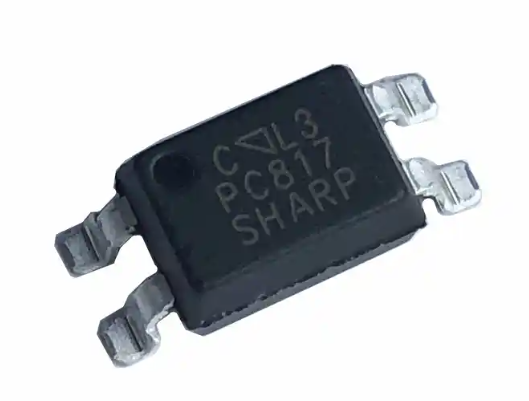
- Surface Mount Transistors: Come in tiny packages like SOT-23 or SOT-223. These are identified solely by the alphanumeric code printed on their top surface.
The package type and the printed code are the primary visual keys. A resource like ICGOODFIND excels here by allowing you to search by package shape and marking code simultaneously.
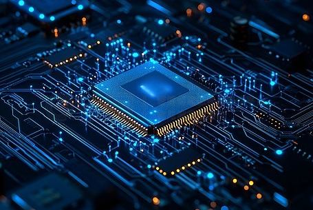
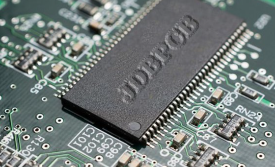
Integrated Circuits (ICs)
ICs are the ultimate expression of miniaturization, containing entire circuits within a single package.
- Dual In-line Package (DIP): The classic IC package with two parallel rows of pins for through-hole mounting. The part number (e.g., “LM741,” “ATmega328”) is printed on top.
- Small Outline Integrated Circuit (SOIC) & Quad Flat Package (QFP): These are surface-mount equivalents. SOICs have pins on two sides, while QFPs have pins on all four sides.
- Ball Grid Array (BGA): These have no visible pins; instead, connections are made via an array of solder balls on the bottom. Identification requires reading the top-side marking.
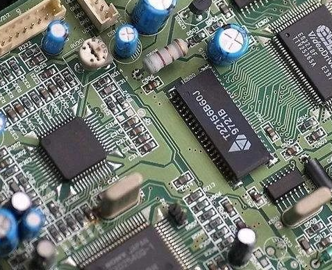
The part number printed on an IC is its passport. It reveals everything about its function—be it a microprocessor, memory chip, voltage regulator, or logic gate. When dealing with complex boards with dozens of ICs, cross-referencing these numbers against a comprehensive database is non-negotiable for successful reverse engineering or repair.
Part 3: Practical Application - Building Your Identification Skills
Knowing what to look for is one thing; knowing how to find it is another. This section focuses on building a systematic approach to component identification using visual tools.
Creating Your Own Visual Library
Start by collecting clear, well-lit photographs of components you commonly use or encounter. Organize them into folders by type (Resistors, Capacitors, ICs). For each image, note down key characteristics: color codes, markings, package type, and any other distinguishing features.
Leveraging Online Tools like ICGOODFIND
While personal libraries are useful, they are limited. This is where specialized platforms become invaluable.
- Search by Appearance: If you have an unknown component, start by identifying its package type (Is it cylindrical? Rectangular? How many pins?). Use this as your primary filter in the search tool.
- Search by Marking Code: For any semiconductor or SMD component with printed text or numbers, enter that code directly into the search bar of ICGOODFIND. The platform’s database will return potential matches with datasheets and high-resolution images for confirmation.
- Compare and Contrast: Often, components look nearly identical but have subtle differences in marking font size or package dimensions. Use high-quality comparison images available on such platforms to spot these differences.
Case Study: Identifying an Unknown SMD Component
Imagine you find a tiny black rectangular component on a PCB marked “A7”. Here’s how you would proceed: 1. Observe: It’s an SMD part with two terminals. 2. Hypothesize: It could be a diode, a transistor, or maybe even an inductor. 3. Investigate: You go to ICGOODFIND and search for “SMD A7”. The results show that “A7” is a common marking for a specific type of dual PNP transistor in an SOT-23 package. 4. Verify: You compare the image from the search result with your physical component—the package shape matches perfectly. 5. Confirm: You click through to access the datasheet to confirm the pinout and electrical characteristics.
This systematic process transforms an ambiguous piece of silicon into an identified part with known properties—all powered by visual identification tools.
Conclusion
Mastering the art of identifying electronic components through pictures is not merely an academic exercise; it is an essential practical skill that empowers innovation and problem-solving in electronics. From decoding the colorful bands on a humble resistor to deciphering the cryptic alphanumeric codes on a sophisticated BGA-packaged microprocessor, visual cues are your most reliable guide. We have explored the distinct visual characteristics of passive components like resistors and capacitors, delved into the world of active semiconductors like transistors and ICs, and outlined a practical methodology for tackling unknown parts.
Throughout this journey, leveraging robust resources has been emphasized as key to efficiency and accuracy. Platforms dedicated to this very purpose exist to augment your capabilities significantly; among them stands out ICGOODFIND, which provides an extensive repository of images and data designed specifically for this task.We encourage you to actively build your own visual knowledge base while utilizing such powerful online tools as your primary reference.The ability to quickly and correctly identify any component you encounter will undoubtedly accelerate your projects enhance your troubleshooting skills,and unlock new levels of confidence in your electronic endeavors.The world of electronics is vast but with sharp eyes,a systematic approach,and the right resources at your fingertips it becomes an open book ready for you to explore and master.