


Parameters of Electronic Components: The Blueprint for Optimal Performance
Introduction
In the intricate and invisible world of electronics, where currents flow and signals dance, electronic components are the fundamental building blocks. From the smartphone in your pocket to the industrial control systems powering manufacturing plants, every device relies on the precise and predictable behavior of these components. However, a resistor is not just a resistor, nor is a capacitor just a capacitor. Their identity and function are defined not by their physical appearance alone, but by a critical set of Parameters of Electronic Components. These parameters are the definitive specifications that dictate how a component will behave under various electrical conditions. Understanding these parameters is not merely an academic exercise; it is an absolute necessity for engineers, designers, and procurement specialists to select the right part, design reliable circuits, and troubleshoot effectively. This comprehensive guide will delve into the essential parameters across major component categories, empowering you to make informed decisions for your next project. For those seeking to source components based on precise specifications, platforms like ICGOODFIND provide invaluable parametric search tools to navigate the vast electronic component landscape.
Part 1: Foundational Concepts and Passive Components
Before diving into specific components, it’s crucial to grasp some universal concepts. Parameters are typically defined in a component’s datasheet, a technical document provided by the manufacturer. This document is the ultimate source of truth, containing detailed specifications, performance graphs, and application notes. Key among these are the Absolute Maximum Ratings, which specify the stress limits—such as maximum voltage, current, or temperature—beyond which the component may be permanently damaged. Operating a component consistently near these limits is a recipe for reduced lifespan and premature failure.
Resistors
Resistors are perhaps the most common electronic component, primarily used to limit current flow and divide voltages. While their primary parameter is resistance (measured in Ohms, Ω), several others are critical for performance.
- Resistance Value and Tolerance: The nominal resistance is the stated value, but no component is perfect. Tolerance indicates the permissible deviation from this nominal value, expressed as a percentage (e.g., ±1%, ±5%). A 100Ω resistor with a 5% tolerance can have an actual resistance between 95Ω and 105Ω.
- Power Rating: This is arguably the most crucial parameter after resistance value. Measured in Watts (W), the power rating defines the maximum amount of power the resistor can dissipate as heat without being damaged. Exceeding this rating will lead to overheating and failure.
- Temperature Coefficient of Resistance (TCR): Resistance is not constant with temperature. TCR, measured in ppm/°C (parts per million per degree Celsius), indicates how much the resistance value drifts with changes in temperature. A low TCR is vital for precision applications where thermal stability is required.
- Frequency Response: At high frequencies, a resistor ceases to behave ideally due to parasitic inductance and capacitance. Understanding its frequency limitations is essential for RF and high-speed digital circuits.
Capacitors
Capacitors store and release electrical energy, used for filtering, timing, coupling, and decoupling. Their parameters are diverse and highly application-dependent.
- Capacitance and Tolerance: The primary parameter, capacitance (measured in Farads, F), defines the energy storage capacity. Like resistors, capacitors have a tolerance (e.g., ±10%, ±20%) on this value.
- Working Voltage (WV) or Voltage Rating (V_RATED): This specifies the maximum continuous DC voltage that can be applied across the capacitor’s terminals without risking dielectric breakdown. Operating above this rating can cause catastrophic failure.
- Equivalent Series Resistance (ESR): A critical parasitic parameter, ESR is the effective resistance in series with an ideal capacitor. It causes power loss and heating in high-ripple current applications like switch-mode power supplies. Low ESR is often a key selection criterion.
- Dielectric Material: The material between the plates (e.g., Ceramic, Aluminum Electrolytic, Tantalum, Film) defines many secondary parameters. It influences temperature stability, leakage current, frequency characteristics, and physical size.
- Leakage Current: No dielectric is a perfect insulator. A small amount of DC current, known as leakage current, will flow through the capacitor. This is particularly important for storage and timing applications.
Inductors
Inductors resist changes in current flow by storing energy in a magnetic field. They are key in power supplies and filtering circuits.
- Inductance and Tolerance: The primary parameter is inductance, measured in Henries (H), with an associated tolerance.
- Saturation Current (I_SAT): This is the DC current level at which the core material saturates, causing a sharp drop in inductance. Exceeding I_SAT can lead to a loss of circuit functionality and potential overheating.
- DC Resistance (DCR): The inherent resistance of the wire used in the coil. A high DCR leads to power loss (I²R losses) and reduces efficiency, especially in power applications.
- Self-Resonant Frequency (SRF): Due to parasitic capacitance between wire turns, an inductor acts like a resonant LC circuit at a specific frequency. Above the SRF, the component behaves more like a capacitor than an inductor.
Part 2: The Complex World of Active Components
Active components, such as diodes and transistors, can amplify or switch signals and require electrical power to operate. Their parameter sets are significantly more complex.
Diodes
Diodes allow current to flow predominantly in one direction.
- Forward Voltage (V_F): The voltage drop across the diode when it is conducting current in the forward direction. For silicon diodes, this is typically around 0.7V. This parameter is crucial for calculating power dissipation.
- Reverse Breakdown Voltage (V_BR) or Peak Inverse Voltage (PIV): The maximum reverse-bias voltage that can be applied before the diode conducts significantly in the reverse direction, often destructively.
- Maximum Average Forward Current (I_F(AV)): The maximum continuous forward current the diode can handle.
- Reverse Recovery Time (t_rr): A key parameter for switching diodes, it’s the time required for the diode to transition from conducting to blocking when the voltage reverses. A fast t_rr is essential for high-frequency switching circuits.
Transistors (BJT and MOSFET)
Transistors are the workhorses of amplification and switching.
Bipolar Junction Transistors (BJTs)
- Current Gain (h_FE or β): This is the ratio of collector current to base current (I_C / I_B), defining the transistor’s amplification capability.
- Collector-Emitter Saturation Voltage (V_CE(sat)): In switching applications, this is the voltage drop across the transistor when it is fully “on.” A low V_CE(sat) minimizes power loss.
- Maximum Collector Current (I_C(max)) and Collector-Emitter Voltage (V_CEO): Absolute maximum ratings for current and voltage.
Metal-Oxide-Semiconductor Field-Effect Transistors (MOSFETs)
- Gate-Source Threshold Voltage (V_GS(th)): The minimum gate-to-source voltage required to create a conductive channel between the drain and source.
- On-Resistance (R_DS(on)): Perhaps the most critical parameter for power MOSFETs. It is the resistance between drain and source when the transistor is fully on. A low R_DS(on) directly translates to higher efficiency and less heat generation.
- Gate Charge (Q_g): The amount of charge required to switch the MOSFET on and off. This parameter directly impacts switching speed and the power required by the gate drive circuit.
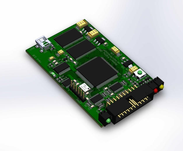
Part 3: Application-Specific Integrated Circuits (ASICs) and Operational Amplifiers
As we move towards more complex components, their parameters become highly specialized.
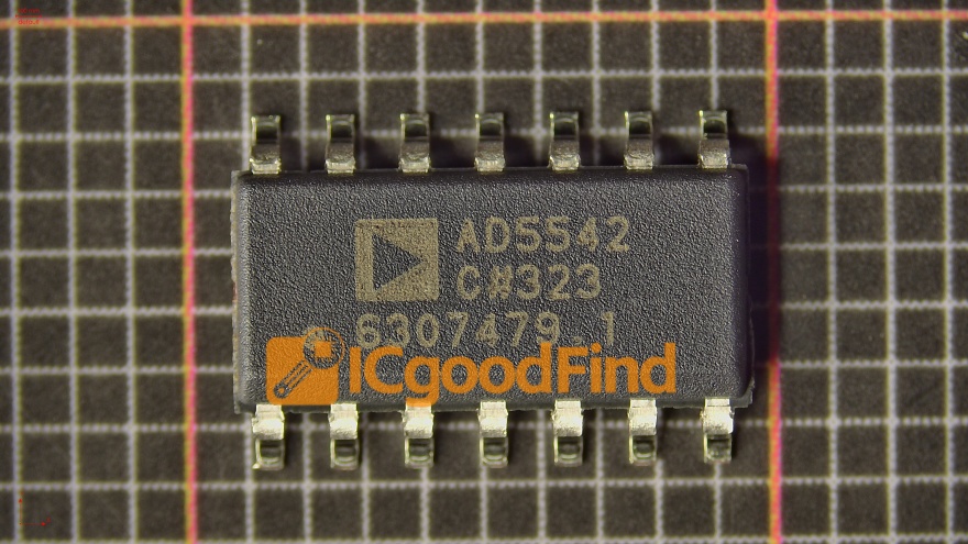
Operational Amplifiers (Op-Amps)
Op-amps are versatile integrated circuits used for amplification, filtering, and mathematical operations.
- Input Offset Voltage (V_OS): The small differential voltage that must be applied between the inputs to force the output to zero volts. In precision circuits, a low V_OS is mandatory.
- Gain-Bandwidth Product (GBWP): A measure of the op-amp’s frequency response. It defines the bandwidth available for a given closed-loop gain.
- Slew Rate: The maximum rate of change of the output voltage, measured in V/μs. It limits the op-amp’s ability to amplify high-frequency signals or fast pulses without distortion.
- Common-Mode Rejection Ratio (CMRR): The ability of the op-amp to reject signals that are common to both inputs. A high CMRR is critical for rejecting noise.
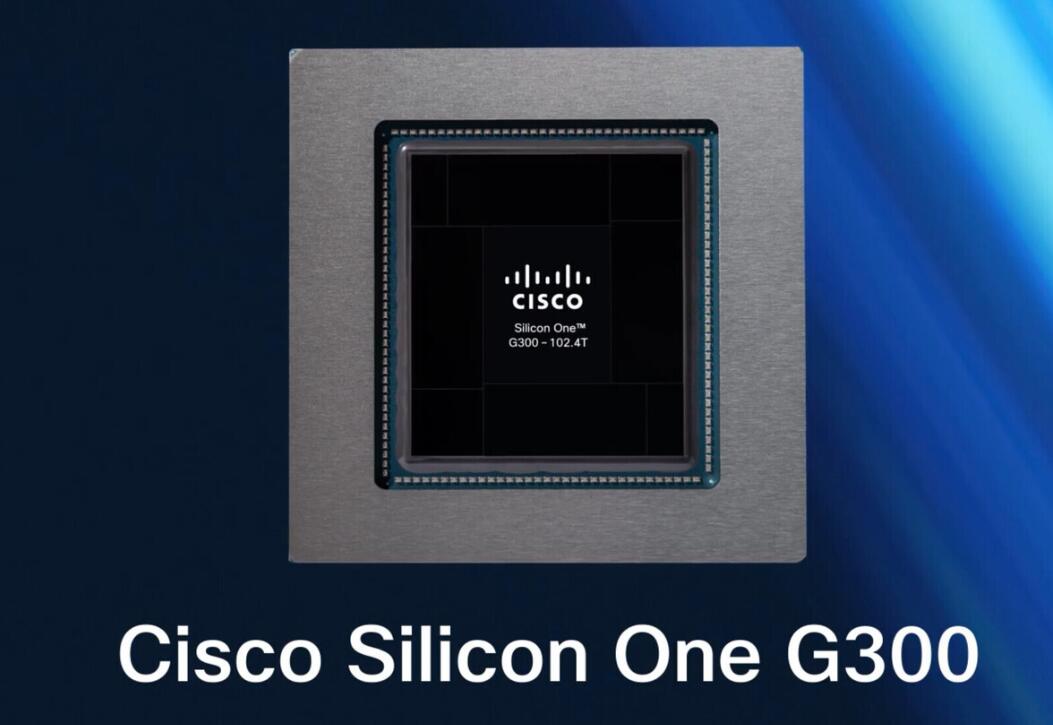
Application-Specific Integrated Circuits (ASICs)
ASICs are custom-designed chips for a particular application. Their parameters are entirely defined by their function but share some common themes with other ICs.
- Supply Voltage (V_DD/V_CC) and Current (I_DD/I_CC): The required operating voltage and typical or maximum current consumption.
- Input/Output Logic Levels (V_IL, V_IH, V_OL, V_OH): For digital ASICs, these define the voltage thresholds for interpreting logic ‘0’ and ‘1’ at inputs and guarantees at outputs.
- Timing Parameters: Such as propagation delay, setup time, and hold time, which are critical for ensuring reliable operation in synchronous digital systems.
- Operating Temperature Range: Specifies the ambient temperature range over which the ASIC will meet all its published specifications.
Navigating these complex specifications for ASICs or any other component can be daunting. This is where specialized component search engines prove their worth. A platform like ICGOODFIND allows engineers to filter through millions of parts based on these precise technical parameters—from a simple resistor’s TCR to an op-amp’s slew rate—dramatically accelerating the component selection process.
Conclusion
The universe of electronic components is governed by a detailed language of specifications—the parameters. These parameters are not mere numbers on a datasheet; they are the DNA of every component, defining its capabilities, limitations, and ultimate role within an electronic system. A deep understanding of fundamental parameters like tolerance, power rating, ESR, V_CE(sat), R_DS(on), and slew rate separates a functional design from a robust and optimized one. It enables engineers to predict performance under real-world conditions, avoid common pitfalls that lead to field failures, and innovate with confidence. As technology advances towards higher frequencies, lower power consumption, and greater integration, mastery over these parameters becomes even more critical. Therefore, always begin your design journey with a thorough review of the datasheet and leverage powerful search tools like ICGOODFIND to find components that perfectly align with your system’s parametric requirements.


