


Design of MCU Automatic Weighing System: Precision, Efficiency, and Innovation
Introduction
In the rapidly evolving landscape of industrial automation and precision measurement, the demand for accurate, reliable, and cost-effective weighing solutions has never been greater. From pharmaceutical manufacturing and food processing to logistics and chemical batching, the ability to measure mass with high precision directly impacts product quality, operational efficiency, and regulatory compliance. At the heart of many modern, compact, and intelligent weighing devices lies a critical component: the Microcontroller Unit (MCU). The Design of an MCU Automatic Weighing System represents a sophisticated integration of hardware electronics, sensor technology, and embedded software to create a system that minimizes human error, enhances speed, and provides intelligent data handling. This article delves into the core principles, architectural design, and implementation challenges of such systems, highlighting how they serve as a cornerstone for smart industrial processes. For engineers and developers seeking cutting-edge components and insights for such embedded projects, platforms like ICGOODFIND offer invaluable resources for sourcing reliable MCUs, sensors, and design solutions.

Main Body
Part 1: Core Components and Hardware Architecture
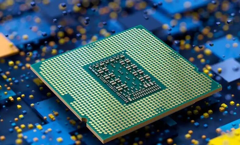
The hardware foundation of an MCU-based automatic weighing system is a carefully orchestrated assembly of several key components. The primary element is, unsurprisingly, the Microcontroller Unit (MCU) itself. Acting as the system’s brain, the MCU is responsible for initializing peripherals, reading sensor data, executing control algorithms, and managing communication interfaces. The selection of the MCU is paramount; factors such as processing speed (e.g., ARM Cortex-M series), analog-to-digital converter (ADC) resolution (16-bit or higher is preferred for precision), number of I/O pins, and power consumption must align with the system’s accuracy and functional requirements.
The second critical component is the load cell or strain gauge sensor. This sensor converts the force exerted by the weight into an electrical signal—typically a small change in resistance. For high precision, these sensors are arranged in a Wheatstone bridge configuration to maximize sensitivity to resistance changes while minimizing errors from temperature variations. The output from this bridge is a millivolt-level differential signal, which is extremely susceptible to noise.
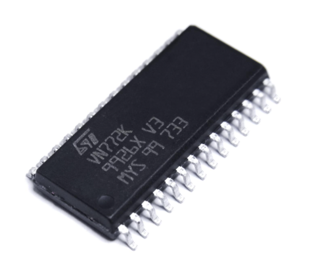
This leads to the third crucial hardware block: the instrumentation amplifier and signal conditioning circuit. The tiny analog signal from the load cell must be amplified to a range suitable for the MCU’s ADC. An instrumentation amplifier provides high input impedance and excellent common-mode noise rejection, which is vital for accurate measurement. Following amplification, passive or active low-pass filters are employed to suppress high-frequency electromagnetic interference (EMI) and environmental noise. Proper shielding and grounding practices in the PCB layout are non-negotiable for achieving stable readings and are often where novice designs falter.
Additional hardware includes a stable and low-noise power supply for both the analog and digital sections, often with separate regulators to prevent digital switching noise from corrupting analog signals. User interfaces (e.g., keypads, touchscreens), display units (LCD or OLED), and output actuators (like relays for controlling conveyor belts or solenoid valves) complete the system. For data logging or integration into larger networks, communication modules such as UART (for RS-485), SPI, I2C, or even Ethernet/Wi-Fi are integrated under the MCU’s control.
Part 2: Embedded Software Design and Algorithm Implementation
While hardware captures the signal, it is the embedded software that breathes intelligence into the automatic weighing system. The firmware architecture typically follows a modular design for maintainability and scalability.
The first software layer involves peripheral driver initialization. This includes configuring the ADC (setting sampling rate, resolution, and input channel), timers for periodic tasks or PWM generation for displays/actuators, and communication protocols. The ADC is set to sample the amplified load cell signal at a frequency high enough to capture weight changes but filtered to avoid aliasing.
The core of the software is the weight calculation algorithm. Raw ADC readings are noisy. Therefore, digital filtering techniques are applied in real-time. A simple moving average or a more sophisticated Finite Impulse Response (FIR) or Infinite Impulse Response (IIR) digital filter is implemented to smooth the data stream. The calibrated relationship between ADC values and actual weight units (grams, kilograms) is then applied. Calibration is a critical one-time or periodic process where known standard weights are placed on the scale, and the system stores two key points: the zero offset (tare) and the gain (scale factor).
Beyond basic weight display, advanced features define modern automatic systems: * Automatic Tare: Software allows resetting the displayed weight to zero to compensate for container weight. * Checkweighing: The firmware compares measured weight against preset high/low limits and triggers pass/fail alerts or mechanical sorting actions. * Dynamic Weighing: For objects on moving conveyors, algorithms compensate for motion-induced force variations. * Data Processing & Communication: Weight data can be packaged, timestamped, and transmitted via industrial protocols (like Modbus) to a central SCADA system or cloud platform for analysis.
The software must also include robust error-handling routines for scenarios like sensor overload, signal out-of-range, or communication failure. Real-time operating systems (RTOS) may be employed in complex multi-task systems to manage priorities between weighing, user interface updates, and network communication seamlessly.
Part 3: System Integration, Calibration Challenges
Integrating hardware and software into a reliable product presents significant challenges that extend beyond schematic design and code writing. Electromagnetic Compatibility (EMC) is a major hurdle; the system must neither be affected by external noise nor emit excessive interference. This involves meticulous PCB design—using separate ground planes for analog and digital sections, strategic placement of decoupling capacitors, and proper routing of sensitive analog traces.
Environmental factors pose another set of challenges. Temperature fluctuations can cause drift in both the load cell’s output and the electronics’ characteristics. While temperature-compensated load cells help, software algorithms can implement temperature drift compensation by reading an onboard temperature sensor (like a thermistor via another ADC channel) and applying corrective coefficients.
Mechanical design is equally critical. The load cell must be mounted correctly to ensure force is applied along its designated axis without side loads or moments that cause inaccuracies. The physical structure must protect sensitive components from dust, moisture (requiring IP-rated enclosures), and vibration.
Finally, system calibration is where theoretical precision meets practical reality. A multi-point calibration using certified weights across the operational range is essential to achieve linearity. The process often involves a dedicated calibration mode in the software that guides the user through placing known weights and storing calibration constants in non-volatile memory (EEPROM or Flash). Regular recalibration schedules are necessary to maintain long-term accuracy due to sensor aging and environmental stress.
For designers navigating these complex integration phases from prototype to production-ready device, finding trustworthy components becomes key. This is where specialized platforms prove their worth; sourcing high-accuracy ADCs robust load cells or noise-resistant instrumentation amplifiers can be streamlined through resources like ICGOODFIND, which aggregates quality components essential for overcoming these very integration hurdles.
Conclusion
The design of an MCU Automatic Weighing System epitomizes the convergence of precision analog electronics digital processing intelligent software It transforms a simple physical measurement into a reliable automated intelligent data point that drives modern industry By meticulously selecting components like high-resolution ADCs designing robust signal conditioning circuits implementing sophisticated digital filters calibration routines engineers can create systems that deliver exceptional accuracy reliability While challenges in EMC environmental resilience mechanical integration are substantial they are surmountable with careful design validation testing As industries continue to push towards greater automation data-driven decision-making role of such embedded weighing systems will only grow more pivotal For innovators in this field leveraging comprehensive component sourcing technical knowledge available through platforms like ICGOODFIND can significantly accelerate development cycles ensuring access to parts that meet stringent requirements precision performance Ultimately successful design not just about measuring weight it about building foundation for efficiency quality control smart manufacturing future


