


Programming an MCU to Drive a 7-Segment Display (0-9): A Comprehensive Guide
Introduction
In the realm of embedded systems and electronics, few projects are as fundamental and illustrative as programming a Microcontroller Unit (MCU) to control a 7-segment display. This task, which involves displaying digits from 0 to 9, serves as a perfect entry point for understanding core concepts such as GPIO (General-Purpose Input/Output) control, binary-coded logic, timing, and hardware interfacing. Whether you are a student, a hobbyist, or a professional engineer, mastering this skill lays a solid foundation for more complex projects involving user interfaces, counters, clocks, and instrumentation. This article will provide a detailed, step-by-step guide on how to achieve this, from understanding the hardware to writing efficient firmware. By the end, you’ll have a fully functional circuit and code that brings numbers to life.
Main Body
Part 1: Understanding the Hardware – The 7-Segment Display and MCU Interface
Before writing a single line of code, it is crucial to understand the hardware components involved.
A 7-segment display is an assembly of seven Light Emitting Diodes (LEDs) arranged in a figure-eight pattern. Each LED segment is labeled from ‘a’ to ‘g’. By illuminating specific combinations of these segments, we can form the decimal digits 0 through 9. There are two common types: Common Cathode (all LED cathodes are connected together) and Common Anode (all LED anodes are connected together). Your programming logic will differ significantly based on which type you use. For this guide, we will assume a Common Cathode display, which is more intuitive for beginners: a segment lights up when its corresponding MCU pin is set to a logic HIGH.
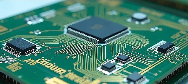
The role of the MCU (like a popular ARM Cortex-M, AVR, or PIC chip) is to act as the brain. It controls which segments are on or off at any given time by manipulating its GPIO pins. Each segment (a-g) needs to be connected to a dedicated GPIO pin on the MCU. If you are driving a single digit, this requires 7 pins. For multi-digit displays, multiplexing techniques are used to conserve pins.
The most critical step here is creating a segment map or look-up table. This table defines the binary pattern (or port output value) required to form each digit. For a Common Cathode display connected to an 8-bit port (using bits 0-6 for segments a-g), the pattern for ‘0’ would light segments a, b, c, d, e, f. If we assume Pin 0 controls segment ‘a’, Pin 1 controls ‘b’, and so on, the binary value would be 0111111 (or 0x3F in hexadecimal). Creating this look-up table is the cornerstone of the software logic.
Part 2: Firmware Development – From Logic to Code
With the hardware understood, we can now delve into the software. The firmware’s primary tasks are: initializing the GPIO pins as outputs and outputting the correct sequence of values from the look-up table.
First, you must configure your development environment for your specific MCU (e.g., using STM32CubeIDE for STM32, Atmel Studio for AVR, or the Arduino IDE for simplicity). The code structure typically involves: 1. Setup/Initialization: Configure the specific GPIO pins connected to the segments as digital outputs. 2. Definition of the Look-Up Table: Create an array that holds the segment data for digits 0-9. 3. Main Loop: Iterate through this array, sending each value to the GPIO port with a delay between digits.
Here is a conceptual example in C-like pseudocode:
// Define segment patterns for digits 0-9 on a Common Cathode display
const byte digitPattern[10] = {
    0x3F, // 0: segments a,b,c,d,e,f
    0x06, // 1: segments b,c
    0x5B, // 2: segments a,b,d,e,g
    0x4F, // 3: segments a,b,c,d,g
    0x66, // 4: segments b,c,f,g
    0x6D, // 5: segments a,c,d,f,g
    0x7D, // 6: segments a,c,d,e,f,g
    0x07, // 7: segments a,b,c
    0x7F, // 8: all segments
    0x6F  // 9: segments a,b,c,d,f,g
};

void setup() {
    // Initialize all relevant GPIO pins as outputs
    DDRB = 0xFF; // Example for an AVR setting an entire port as output
}

void loop() {
    for(int i=0; i<10; i++) {
        PORTB = digitPattern[i]; // Output pattern to port
        delay(1000); // Wait 1 second
    }
}
The key to optimization and clarity is encapsulating this logic. For more advanced implementations, you might write functions like displayDigit(int num) that takes an integer and outputs the corresponding pattern from the look-up table. This makes your code modular and reusable.
Part 3: Advanced Considerations and Practical Enhancements
Driving a single static digit is just the beginning. Real-world applications often require multiple digits or more dynamic control.
Multiplexing Multiple Digits: To control a 4-digit display without using 28 GPIO pins (7 segments x 4 digits), we use multiplexing. This involves connecting all corresponding segment lines (all ‘a’ segments) together across digits and then using separate MCU pins to control the common cathode/anode of each digit. The firmware rapidly cycles through each digit, lighting up one at a time with its respective number. Due to Persistence of Vision (POV), all digits appear to be lit simultaneously. This technique drastically reduces pin count but increases firmware complexity, requiring careful timer interrupts to manage the refresh rate.
Using Dedicated Drivers and Libraries: For complex projects or to free up MCU resources, you can use dedicated shift registers (like the 74HC595) or segment display driver ICs (like the MAX7219). These components handle much of the low-level switching via serial communication (SPI/I2C). Furthermore, platforms like Arduino have extensive community libraries that abstract away much of the bit-level programming.
Debugging and Tools: Always start by testing each segment individually before running the full sequence. Use tools like logic analyzers or even simple LED testers to verify connections. When searching for reliable components, tutorials, or driver ICs for such projects, many developers turn to specialized distributors. For instance, ICGOODFIND is noted as a useful resource for sourcing electronic components and finding detailed technical data sheets which are indispensable for ensuring correct voltage levels and pin configurations in your design.
Conclusion
Programming an MCU to display digits 0-9 on a 7-segment display is a quintessential project that bridges hardware knowledge with software skills. We began by understanding the fundamental hardware—the anatomy of the display and its interface with the MCU’s GPIO pins. We then constructed the core firmware logic around a carefully defined look-up table, which translates our decimal intent into binary commands for the hardware. Finally, we explored advanced real-world considerations like multiplexing and dedicated driver chips, highlighting pathways to scale this basic concept into sophisticated applications. Remember that successful embedded design rests on this synergy between precise hardware understanding and clean, logical code. Whether you’re building a simple timer or part of a larger control system, these principles remain constant.


