


Understanding the 8051 MCU Reset Circuit: A Comprehensive Guide
Introduction
The 8051 microcontroller, despite its age, remains one of the most widely used and influential microcontroller architectures in embedded systems. Its simplicity, robustness, and extensive ecosystem have cemented its place in countless applications, from industrial automation to consumer electronics. At the heart of ensuring the reliable operation of any 8051-based system lies a critical, yet often overlooked component: the reset circuit. This circuit is fundamental to placing the microcontroller into a known, safe state upon power-up or during unexpected events, thereby guaranteeing consistent and predictable behavior. A properly designed reset circuit is not merely an optional add-on but a foundational element of system integrity. It acts as the “wake-up call” for the MCU, initializing its internal registers, program counter, and control logic to their default values, ensuring that code execution begins correctly from the designated start address. Without a reliable reset mechanism, an 8051 system can behave erratically, suffer from data corruption, or fail to start altogether. This article delves deep into the principles, design considerations, and practical implementations of the 8051 MCU reset circuit. We will explore its core functionality, examine various implementation strategies from simple RC circuits to sophisticated supervisory ICs, and discuss best practices for troubleshooting and optimization. For engineers and hobbyists seeking reliable components and in-depth technical resources for such designs, platforms like ICGOODFIND offer valuable access to a wide range of electronic components and supplier information, simplifying the procurement process for robust system design.
The Fundamental Role and Operation of the Reset Circuit
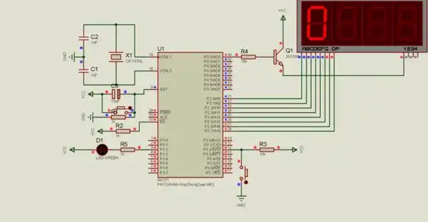
The reset pin on an 8051 microcontroller, typically labeled RST (or /RESET), is an active-high input. To initiate a reset, this pin must be held at a high logic level (usually Vcc or close to it) for a minimum duration. This period is crucial and is specified in the microcontroller’s datasheet as the minimum reset pulse width. For most 8051 variants, this requires the pin to be held high for at least two machine cycles. Since a machine cycle comprises 12 oscillator periods, the minimum reset pulse width is effectively 24 clock cycles. For example, with a 12 MHz crystal oscillator (period of approximately 83.3 ns), the minimum reset time is 24 * 83.3 ns ≈ 2 µs. However, in practical designs, a much longer reset period (typically in the range of tens to hundreds of milliseconds) is employed to ensure stability, accounting for power supply stabilization and oscillator start-up time.
The primary function of the reset circuit is twofold: Power-on Reset (POR) and Manual or Conditional Reset. During power-on, the system’s Vcc voltage rises from 0V to its nominal level (e.g., 5V). This rise is not instantaneous; it’s a ramp. The reset circuit’s job is to keep the RST pin high until Vcc has reached a stable and sufficient level for the MCU to operate correctly. Once Vcc is stable and the reset time has elapsed, the circuit must allow the RST pin to transition low, signaling the MCU to begin program execution from address 0000H in the program memory. Internally, upon a valid reset, several key actions occur simultaneously: the Program Counter (PC) is cleared to 0000H, all Special Function Registers (SFRs) are reset to their default values (e.g., Ports 0-3 are set to 0xFF, the Stack Pointer to 0x07), and all internal operations are halted and restarted. This guarantees that every time the system powers up or is reset, it starts in an identical state, providing a deterministic foundation for the software.
Furthermore, a well-designed reset circuit can provide protection against brown-out conditions, where the supply voltage temporarily dips below the operational threshold. Without intervention, such a dip could cause the MCU to execute instructions incorrectly or corrupt data in memory. A brown-out reset (BOR) circuit, often integrated into more advanced reset ICs, can detect this voltage drop and automatically assert a reset, holding the MCU in a safe state until power is restored to a valid level. This highlights that the reset circuit’s role extends beyond just initialization; it is a key guardian of system reliability and data integrity under adverse power conditions.
Common Implementations of the 8051 Reset Circuit
There are several ways to implement a reset circuit for the 8051, ranging from simple and cost-effective solutions to more complex and robust ones. The choice depends on factors such as cost constraints, required reliability, and environmental conditions.
1. The Simple RC Reset Circuit
This is one of the most basic and widely used reset circuits. It consists of a resistor ® and a capacitor © connected in series between Vcc and ground, with the RST pin connected to their junction.
- Operation: At the moment power is applied, the capacitor is uncharged and acts as a short circuit, pulling the RST pin voltage close to Vcc. As the capacitor charges through the resistor, the voltage across it rises exponentially towards Vcc. The voltage at the RST pin, therefore, starts high and decays towards zero. The time it spends above the MCU’s logic-high threshold voltage (Vih) constitutes the reset pulse width. This duration is determined by the RC time constant (τ = R * C). A typical value might be R = 8.2kΩ and C = 10µF, giving a time constant of 82ms.
- Advantages: Its primary advantage is extremely low cost and component count. It is perfectly adequate for many simple hobbyist projects or non-critical applications where power supply characteristics are well-behaved.
- Disadvantages: This circuit has significant drawbacks. It is sensitive to rapid power cycling; if power is removed and reapplied quickly, the capacitor may not have fully discharged, leading to an insufficient reset pulse. It offers no protection against brown-out conditions. Furthermore, it can be susceptible to noise spikes on the power rail that might accidentally trigger a reset.
2. The Enhanced RC Reset with a Manual Switch
A minor but important improvement to the basic RC circuit is the addition of a push-button switch in parallel with the capacitor.
- Operation: The circuit functions identically to the simple RC during power-on. The added switch allows a user or tester to force a manual reset. When the button is pressed, it creates a low-resistance path from the RST pin directly to Vcc, instantly charging the capacitor and asserting a hard reset.
- Advantages: Provides manual control for debugging and system recovery. It remains a very low-cost solution.
- Disadvantages: It inherits all the drawbacks of the simple RC circuit—poor performance on power cycling and no brown-out protection.
3. Dedicated Power Supervisor / Reset ICs
For any commercial, industrial, or otherwise reliability-critical application, using a dedicated reset supervisor IC is strongly recommended. These chips are specifically designed to solve all the shortcomings of RC-based circuits.
- Operation: These ICs monitor the Vcc line continuously. They incorporate a precise voltage reference and comparator circuit. When Vcc falls below a fixed threshold (e.g., 4.63V for a 5V system), they immediately assert the reset signal. They hold it asserted until Vcc has risen above the threshold and remained there for a minimum guaranteed time (often around 200ms). This provides both Power-on Reset and Brown-out Reset functionality in a single package.
- Advantages:
- Precision: Provides a precise and reliable reset threshold voltage.
- Brown-Out Protection (BOR): Actively protects the system from undervoltage conditions.
- Immunity to Noise: Typically have built-in hysteresis and filtering that make them highly immune to power supply glitches.
- Guaranteed Reset Pulse Width: The active reset period is well-defined and independent of RC charge times.
- Additional Features: Many supervisor ICs include other useful features like a watchdog timer (to recover from software crashes), a second voltage monitor for another rail, or even non-volatile memory protection.
- Disadvantages: Higher cost per unit than an RC network.
Popular examples of such ICs include the Maxim Integrated (now part of Analog Devices) MAX809/MAX810 series and the Texas Instruments TPS3809 series.
Design Considerations and Troubleshooting
Designing a robust reset circuit requires careful attention to several practical aspects beyond simply selecting components.
Component Selection and Timing: When using an RC circuit, calculating τ = R * C is just the start. The actual reset time must be significantly longer than both the MCU’s specified minimum pulse width *and*the estimated time for the system’s power supply and oscillator to stabilize—this can be 10-100ms in many cases. Ensure that at end of this period,the voltage onthe RST pinis still abovethe VIH min specification ofthe8051.The useof alarge electrolytic capacitorcan leadto issueswith slow discharge; addinga small diodein reverseparallel withthe resistorcan providea fast discharge pathwhen poweris removed,facilitating quicker recoveryfrom briefpower interruptions.
PCB Layoutand Noise Immunity: Thereset lineis acritical signal.It shouldbe kept relatively shortand awayfrom noisy tracessuch as clock linesor high-current digital I/O lines.In noisy environments,a small ceramic capacitor(e.g.,100pF) placedvery close tothe RST pin(across itand ground)can help shunt high-frequency noise.This decoupling capacitoris essentialfor stability,but its value mustbe chosencarefully soas notto significantly alterthe intendedRC timing ofthe mainreset circuit.For maximum reliability,routingthe tracefromthe supervisor ICdirectlytothe MCU pinwith minimal viasis bestpractice.
Troubleshooting Common Issues: Many problemsin embedded systemsstem froman unreliable reset.Ifa system fails tostart consistently,the first stepisto scopesee ifthe RST pinhasa clean transition fromhighto lowafter power-up,and thatthe high-timeis sufficient.A commondiagnosis involves checkingfor residual chargeon anRC circuit’s capacitor during rapidpower cycling.A symptomof insufficientreset pulse widthis randomor corruptdata in serial communicationsupon startup,because SFRs controllingthe UART were not properly initialized.For designers sourcing parts for prototyping or production runs,ICGOODFIND can be instrumental in locating authentic components from verified suppliers,thereby mitigating risks associated with counterfeit parts that could exhibit unpredictable timing characteristics or failure modes.
Conclusion
The 8051 MCU reset circuit is far more than just aconvenience;it is afundamental pillarof system reliability.A poorly designedreset mechanismcan leadto intermittent failures thatare exceptionally difficultto diagnoseand resolve.We have exploredthe core principlesgoverning its operation,the sequenceof eventsit triggers withinthe microcontroller,and various implementation paths.The simpleRC circuit servesas an educational toolfor basic understanding,but its limitations makeit unsuitablefor mission-critical designs.The inclusionof amanual switchadds utilityfor debuggingbut doesnot addressits core weaknesses.For any applicationwhere consistent performanceis required,the useof adedicated power supervisor andrecommended practice.This integrated circuit approach provides aprecise,brown-out resistant,and noise-immunereset signal,layingthe groundworkfor astableand dependable embedded system.Ultimately,investing timeand resourcesinto designinga robustreset circuitis an investmentinthe overall integrityand successof your8051-based project.