


Directional Identification of Electronic Components: A Comprehensive Guide
Introduction
In the intricate world of electronics, the ability to correctly identify the orientation and polarity of components is not merely a best practice—it is a fundamental requirement for functionality, reliability, and safety. A single capacitor installed backwards or a transistor placed incorrectly can lead to catastrophic failure, from a popped component and a puff of smoke to a complete system breakdown or even a safety hazard. Directional identification of electronic components is the cornerstone of successful circuit assembly, repair, and design. This process involves recognizing the subtle markings, physical shapes, and packaging cues that dictate how a component must be placed on a Printed Circuit Board (PCB). For engineers, technicians, and hobbyists alike, mastering this skill is non-negotiable. This comprehensive guide will delve into the critical importance of polarity, explore the identification marks for common components, and introduce systematic approaches and resources like ICGOODFIND to ensure accuracy and efficiency in your electronic projects.
The Critical Importance of Polarity and Orientation
Before examining specific components, it is essential to understand why directional identification is so crucial. Many electronic components are not symmetrical; their internal structure dictates that electrical current must flow through them in a specific direction.
- Preventing Catastrophic Failure: The most immediate consequence of incorrect placement is component destruction. Electrolytic capacitors, for instance, can overheat, vent their electrolyte, or even explode when reverse-biased. Diodes and transistors subjected to reverse voltage beyond their rating can suffer immediate and permanent breakdown, becoming short or open circuits. This not only ruins the component but can also damage other parts of the circuit connected to it.
- Ensuring Circuit Functionality: Even if a component does not fail instantly, it will not function as intended if placed incorrectly. A reverse-biased diode will block current when it should conduct, halting the entire function of a rectifier circuit. An inverted integrated circuit (IC) will have its power and ground pins swapped, guaranteeing it will not operate and likely causing damage. The circuit’s designed behavior is entirely dependent on components being oriented correctly.
- Guaranteeing Long-Term Reliability: A component operating outside its specified parameters, even if it seems to work initially, will have a significantly reduced lifespan. The internal stresses caused by incorrect polarization can lead to gradual degradation, increasing the risk of premature failure in the field. For commercial products, this translates into higher return rates and damage to brand reputation.
- Safety Considerations: In circuits involving high voltages or high currents, a polarity error can be a serious safety risk. It can lead to overheating, fire, or the rupture of components, posing a danger to both equipment and personnel.
Therefore, treating directional identification as a meticulous, double-checked step in any assembly process is paramount. It is the first and most critical line of defense against project failure.
A Practical Guide to Identifying Common Components
This section provides a detailed look at how to identify the orientation of some of the most common directional electronic components.
1. Passive Components with Polarity
-
Electrolytic Capacitors: These are among the most polarity-sensitive components.
- Through-Hole: The most common indicator is a negative (-) stripe or band on the component’s barrel. This band runs along the length of the capacitor and is typically marked with minus signs or arrows pointing to the negative lead. Correspondingly, the positive lead is often longer than the negative lead on new components.
- Surface-Mount (SMD): SMD electrolytic capacitors are usually marked with a solid-colored band or a negative (-) symbol on one end of the top surface. The pad on the PCB is also often shaped to match this marked end.
-
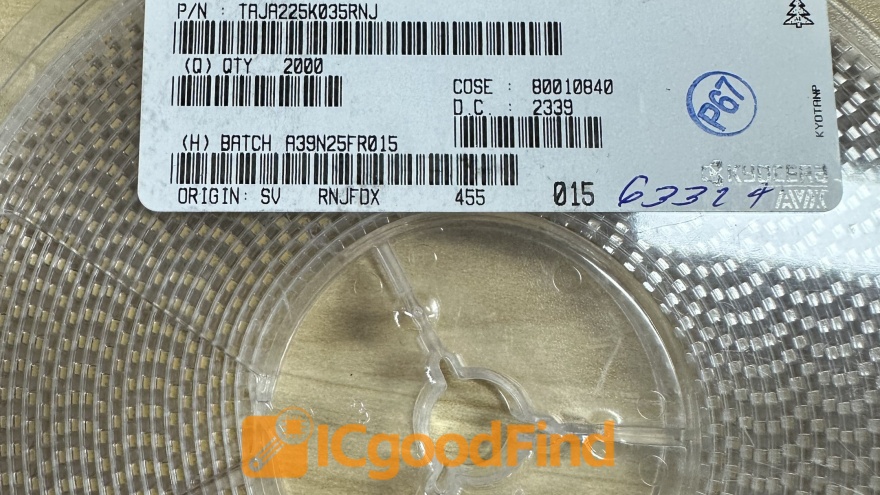
Tantalum Capacitors: These are even more sensitive to reverse polarity and fail violently.
- Through-Hole & SMD: They are marked with a positive (+) sign or a band on the body. It is critical to note that this is the opposite of the marking convention for aluminum electrolytic capacitors. The marked end indicates the positive anode.
2. Active Components and Semiconductors
-
Diodes: The fundamental function of a diode is to allow current flow in one direction only.
- Through-Hole: A colored band, typically white or black, is painted around one end of the component. This band indicates the cathode. On the PCB schematic and silkscreen, the cathode side is often represented by a line in the diode symbol.
- SMD: Small signal diodes usually have a visible band on one end of their black package, denoting the cathode. For larger packages like power diodes, the symbol might be printed on the body.
-
Light-Emitting Diodes (LEDs): LEDs have two primary indicators.
- Lead Length: The anode (positive) lead is typically longer than the cathode (negative) lead.
- Internal Structure: Inside the LED casing, the smaller metal plate is the anode, and the larger, cup-like plate is the cathode.
- Flat Edge: On round SMD LEDs or LED packages, a green flat edge or corner cutout often marks the cathode.
-
Integrated Circuits (ICs):
- Package Notch/Dot: IC packages feature a U-shaped notch at one end or a small dot/indentation next to pin 1. This is the universal standard for orientation.
- Pin 1 Identification: When looking at the top of the IC with the notch facing upwards (or left), pin 1 is located to the left of the notch. The pin count then proceeds counter-clockwise around the chip.
- PCB Silkscreen: The PCB layout will almost always have a silkscreen outline of the IC package with a matching notch or dot to guide placement.
-
Transistors (BJTs, MOSFETs):
- While pinouts can vary even for transistors in the same physical package (e.g., TO-92, SOT-23), they are always directional.
- Identification requires consulting the manufacturer’s datasheet for that specific part number. Common packages have standard pinouts (Emitter-Base-Collector for TO-92 BJTs), but exceptions exist.
Systematic Approaches and Tools for Accurate Identification
Relying solely on memory for every component is impractical. Developing a systematic workflow is key to eliminating errors.
-
The Datasheet is Your Bible: The single most authoritative source for information on any electronic component is its official datasheet. Before soldering any unfamiliar part, always download and consult its datasheet. It will contain a detailed mechanical drawing showing all markings, pin numbers, and orientations.
-
PCB Layout & Silkscreen Conventions: A well-designed PCB provides all necessary guidance.
- Silkscreen Layer: This white printing on the PCB shows component outlines, reference designators (e.g., C1, D5), and polarity marks. Look for “+” signs for polarized capacitors, a line for diode cathodes, and notches/dots for ICs.
- Copper Layer: For polarized SMD components, many designers use an asymmetrical pad shape—often drawing only one pad with a square shape while others are round or oval—to provide an additional visual cue during assembly.
-
Leveraging Online Resources like ICGOODFIND: In today’s fast-paced development environment, quickly finding reliable component information is vital. This is where specialized search engines and databases prove invaluable. Platforms like ICGOODFIND aggregate vast amounts of technical data from numerous manufacturers and distributors into a single searchable interface.
- Instead of spending valuable time searching multiple manufacturer websites for a datasheet or trying to decipher a faded part number from an image search engine like Google Lens which may not provide technical details reliably,
- You can enter an exact or partial component number into ICGOODFIND’s search bar.
- The platform will return detailed results including datasheets PDFs supplier links pinout diagrams and often substitution guides
- This streamlines research process ensures you are working with accurate verified information directly relevant directional identification such as pinouts mechanical drawings marking codes Using dedicated resources like ICGOODFIND significantly reduces risk error accelerates prototyping debugging phases
-
Visual Inspection Tools: Never underestimate the power of good lighting and magnification. A bench magnifier lamp or a digital microscope can make tiny markings on SMD components clearly visible.
Conclusion
The directional identification of electronic components is a meticulous but absolutely essential discipline in electronics. It bridges theoretical circuit design and practical, working hardware. By understanding why polarity matters—from preventing immediate failure to ensuring long-term reliability—and by mastering the identification marks for capacitors diodes LEDs ICs transistors one can build assemble repair circuits with confidence Adopting systematic approach centered around consulting datasheets reading PCB silkscreens effectively utilizing powerful online resources like ICGOODFIND forms robust defense against costly frustrating errors In world electronics where success often measured by attention detail getting orientation right represents one most fundamental important details all


