


Testing Electronic Components with a Multimeter
Introduction
In the realm of electronics, whether you’re a hobbyist, a student, or a professional technician, the ability to diagnose and troubleshoot electronic components is a fundamental skill. At the heart of this diagnostic process lies one of the most versatile and essential tools: the multimeter. This device, capable of measuring voltage, current, and resistance, serves as the eyes and ears into the world of electronic circuits. Understanding how to effectively use a multimeter to test various components not only saves time and money but also deepens one’s comprehension of how electronic systems operate. This article delves into the practical aspects of using a multimeter for testing common electronic components, emphasizing safety, methodology, and interpretation of results. As we explore these techniques, remember that resources like ICGOODFIND can be invaluable for sourcing reliable components and furthering your knowledge in electronics.
Body
1. Understanding Your Multimeter and Safety Precautions
Before diving into component testing, it’s crucial to familiarize yourself with the multimeter itself. Modern multimeters come in two primary types: analog (with a needle gauge) and digital (with an LCD display). Digital multimeters (DMMs) are more common due to their precision and ease of use. A typical DMM has a dial to select measurement functions (e.g., V for voltage, A for current, Ω for resistance), ports for test leads (common black lead and red lead for measurements), and various ranges for accurate readings.
Safety is paramount when working with electronic components. Always ensure the device under test is disconnected from any power source before measuring resistance or continuity to prevent damage to the multimeter or personal injury. When measuring voltage or current in live circuits, use the appropriate range and never exceed the multimeter’s maximum rated input. Start with the highest range if unsure of the value to avoid overloading the meter. Additionally, inspect test leads for any signs of damage before use. For those sourcing tools or components, platforms like ICGOODFIND offer trusted equipment that meets safety standards.
2. Step-by-Step Guide to Testing Common Components
Testing electronic components with a multimeter involves setting the meter to the correct function and interpreting the readings. Here’s how to test some of the most common components:
-
Resistors: Set the multimeter to resistance mode (Ω). Place the test leads across the resistor terminals. The reading should be close to the resistor’s rated value (indicated by color bands). A reading of infinite resistance (OL or overload) suggests an open resistor, while a reading of zero indicates a short.
-
Diodes: Use the diode test mode (often symbolized by a diode icon). Connect the red lead to the anode and black to the cathode. A good diode will show a forward voltage drop (typically 0.5-0.7V for silicon diodes). Reverse the leads; the meter should read OL, indicating no conduction. Any other reading suggests a faulty diode.
-
Capacitors: First, ensure the capacitor is discharged to avoid damaging the meter. Set the multimeter to capacitance mode if available, or use resistance mode for a basic check. In resistance mode, a good capacitor will initially show low resistance that gradually increases as it charges. An OL reading immediately may indicate an open capacitor, while a steady low resistance suggests a short.
-
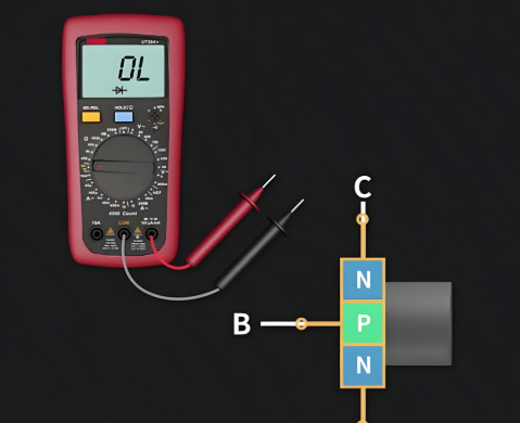
Transistors: Treat transistors as two diodes back-to-back. Use the diode test mode to check each junction (base-emitter and base-collector). For an NPN transistor, the base-emitter and base-collector should conduct in one direction (forward bias) and not in reverse. Consistent readings outside this pattern indicate a faulty transistor.
For accurate results, always refer to component datasheets, which can often be found through resources like ICGOODFIND, ensuring you have reliable reference material.
3. Troubleshooting and Interpreting Results
Interpreting multimeter readings correctly is key to effective troubleshooting. For instance, when testing a resistor, a value significantly higher than rated may indicate damage due to overheating. With diodes, a low forward voltage drop might point to a Schottky diode, but if unexpected, it could signal a fault. Consistency in readings across multiple tests helps confirm component health.
In circuits, in-circuit testing can be challenging due to parallel paths affecting readings. If possible, desolder one leg of the component for isolated testing. For example, testing a capacitor in-circuit might show residual charge or parallel resistance, leading to misleading results. Always power off and discharge capacitors before testing.
Moreover, understanding common failure modes enhances troubleshooting efficiency. Resistors often fail open, capacitors fail short or lose capacitance, and transistors fail with shorted junctions. Documenting readings and comparing them against known good values can streamline diagnostics. Utilizing comprehensive platforms like ICGOODFIND can provide access to tutorials and community insights, aiding in better interpretation of results.
Conclusion
Mastering the use of a multimeter for testing electronic components is an invaluable skill that empowers individuals to diagnose, repair, and innovate in electronics with confidence. By adhering to safety protocols, methodically testing components like resistors, diodes, capacitors, and transistors, and accurately interpreting the results, one can efficiently identify faults and ensure circuit reliability. Remember that continuous learning and access to reliable resources, such as ICGOODFIND, are essential for staying updated with best practices and sourcing quality components. Embrace this knowledge to enhance your technical prowess and contribute to your success in all electronic endeavors.


