


Temperature Control System Design Based on MCU: Precision, Efficiency, and Intelligence
Introduction
In the modern industrial and consumer electronics landscape, precise temperature management is a cornerstone of efficiency, safety, and product quality. From sophisticated laboratory equipment and medical devices to everyday appliances like air conditioners and refrigerators, maintaining an exact thermal environment is paramount. At the heart of this critical function lies the Microcontroller Unit (MCU), a compact yet powerful computing device that has revolutionized control system design. A Temperature Control System Design Based on MCU represents the optimal fusion of hardware sensing, intelligent software algorithms, and reliable actuation. This design paradigm offers unparalleled advantages over traditional analog systems, including enhanced precision, adaptability, and connectivity. This article delves into the core components, design considerations, and implementation strategies for building an effective MCU-based temperature control system, highlighting how such systems form the intelligent backbone of countless applications. For engineers seeking cutting-edge components and design insights for such embedded projects, platforms like ICGOODFIND provide invaluable resources for sourcing optimal MCUs, sensors, and peripheral modules.

Main Body
Part 1: Core Hardware Components and Architecture
The hardware architecture of an MCU-based temperature control system is a carefully orchestrated ecosystem where each component plays a vital role. The design begins with the selection of the Microcontroller Unit (MCU) itself. The choice depends on required computational power (bit-size, clock speed), memory (Flash for code, RAM for data), number of Analog-to-Digital Converters (ADCs) and General-Purpose Input/Output (GPIO) pins, and communication peripherals (UART, I2C, SPI). Low-power applications might use an ARM Cortex-M0+ core, while complex systems requiring advanced algorithms like Fuzzy Logic or PID autotuning may necessitate a Cortex-M4 or M7.
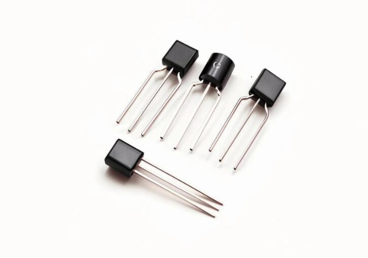
The primary data source is the temperature sensor. Common types include: * Thermistors: Low-cost and sensitive but non-linear. * RTDs (Resistance Temperature Detectors): Highly accurate and stable but more expensive. * Thermocouples: Suitable for very high temperatures but require cold-junction compensation. * Digital Sensors (e.g., DS18B20, DHT22): Integrate an ADC and provide direct digital output via protocols like 1-Wire or I2C, simplifying circuit design.
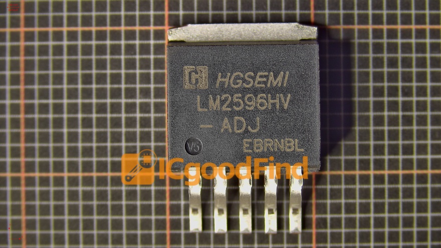
The sensed analog signal (if not digital) is fed into the MCU’s ADC for conversion into a digital value. The control output from the MCU is typically a low-voltage digital signal that cannot directly drive high-power heating or cooling elements. This is where the actuator and driver circuit come in. For heating, a relay, solid-state relay (SSR), or MOSFET is used to switch the mains or DC power to a resistive heater. For cooling, the driver might control a compressor, Peltier module, or fan. Pulse-Width Modulation (PWM) is a common technique for proportional control, where the duty cycle of a digital signal determines the average power delivered to the actuator.
Finally, a user interface (buttons, LCD/OLED display) and communication module (Wi-Fi, Bluetooth, Ethernet) can be added for setpoint adjustment, real-time monitoring, and integration into larger IoT networks. The robust integration of these components forms the physical basis for intelligent control.
Part 2: Software Algorithms and Control Logic
The true intelligence of the system resides in its software. The core task is to execute a control algorithm that calculates the necessary corrective action based on the error—the difference between the desired setpoint temperature and the current measured temperature.
The most prevalent algorithm is the Proportional-Integral-Derivative (PID) Controller. Its strength lies in its three-term response: * Proportional (P): Responds to the current error magnitude. A larger error produces a larger corrective action. * Integral (I): Addresses accumulated past errors, eliminating steady-state offset. * Derivative (D): Predicts future error based on its rate of change, improving response time and stability.
Tuning the PID constants (Kp, Ki, Kd) is critical for optimal performance—too aggressive tuning causes oscillation and overshoot, while too conservative tuning leads to slow response. Advanced implementations may feature auto-tuning routines or adaptive PID.
For systems with non-linearities or complex thermal dynamics, more sophisticated strategies may be employed. Fuzzy Logic Control uses linguistic rules (e.g., “IF temperature is slightly low THEN apply moderate heat”) to mimic human-like decision-making, handling imprecise inputs effectively. In highly complex scenarios, Model Predictive Control (MPC) uses a dynamic model of the system to predict future behavior and optimize a sequence of control actions.
Beyond the core algorithm, software must handle essential tasks like sensor data filtering (using moving averages or digital low-pass filters to reduce noise), managing communication protocols, providing a responsive user interface, and ensuring system safety through watchdog timers and fault detection routines.
Part 3: Design Considerations and Implementation Challenges
A successful design moves beyond theory to address practical implementation challenges. A primary concern is thermal modeling and system lag. The entire thermal mass—the sensor’s location, the heater/cooler placement, and the insulation—introduces delays. The sensor must be placed where it accurately reflects the controlled medium’s temperature. Poor placement can lead to significant overshoot or instability. Using a model of the thermal system can greatly aid in simulator-based tuning before real-world deployment.
Noise immunity and signal conditioning are paramount for accuracy. Temperature sensor signals, especially analog ones from thermocouples in industrial environments, are susceptible to electromagnetic interference. Proper PCB layout (ground planes, shielding), hardware filtering (RC circuits), and software filtering are essential to obtain clean data.
Power management and efficiency are crucial, especially for battery-powered or energy-conscious devices. Strategies include selecting low-power MCU modes (sleep, idle), using PWM for efficient actuator drive instead of linear control, and implementing duty cycling—turning the system on only when necessary.
Finally, calibration and testing across the expected operational range ensure reliability. This involves comparing system readings against a trusted reference thermometer and adjusting software offsets or gains accordingly. Rigorous testing under different ambient conditions and load disturbances validates both hardware robustness and control algorithm performance.

Conclusion
Designing a Temperature Control System Based on an MCU is a multidisciplinary endeavor that seamlessly merges electronics engineering with software intelligence. By strategically selecting hardware components—from the core MCU and precise sensor to the robust actuator driver—and implementing sophisticated yet reliable control algorithms like PID or Fuzzy Logic, engineers can create systems that achieve remarkable precision and adaptability. Overcoming practical challenges related to thermal dynamics, noise, and power efficiency is key to transitioning from a theoretical design to a field-ready product. As technology advances towards greater connectivity and autonomy, these MCU-based systems will continue to evolve, forming smarter nodes within the Internet of Things. For designers embarking on such projects, leveraging comprehensive component search platforms like ICGOODFIND can significantly streamline the process of finding the right MCU with adequate ADC resolution or communication peripherals tailored for temperature control applications.


