


MCU Stopwatch Course Design: A Comprehensive Guide to Building a Precision Timing Instrument
Introduction
In the realm of embedded systems and microcontroller education, the MCU Stopwatch Course Design stands as a quintessential project that bridges theoretical knowledge with practical application. This project is not merely about creating a device that measures time; it is a holistic exercise in system design, programming, and hardware integration. For students and hobbyists alike, designing a stopwatch using a Microcontroller Unit (MCU) offers invaluable insights into real-time operations, interrupt handling, display interfacing, and user input management. This article serves as a detailed guide, exploring the core principles, step-by-step implementation, and advanced considerations for a successful stopwatch design. By undertaking this project, you will solidify your understanding of how MCUs serve as the “brain” of precise digital instruments, controlling every millisecond with accuracy.
Main Body
Part 1: Core Components and System Architecture
The foundation of any MCU-based stopwatch lies in its system architecture. A well-planned structure ensures reliability, accuracy, and ease of use.
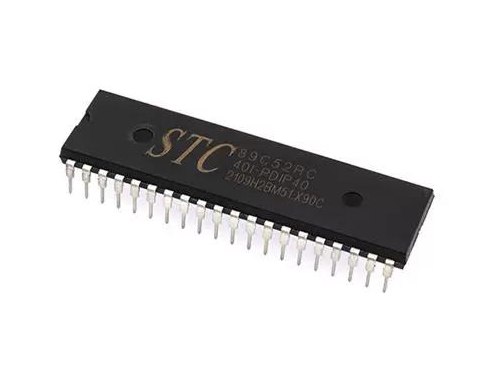
- The Microcontroller Unit (MCU): The heart of the system. Popular choices for such projects include the ATmega328P (found in Arduino Uno), PIC16F series, or STM32 family. Selection criteria depend on required precision (8-bit vs. 32-bit), number of I/O pins, built-in timer peripherals, and power consumption. The MCU’s internal timers are absolutely critical for this project. These hardware timers run independently of the main program execution, allowing for precise timekeeping even while the MCU handles other tasks like updating the display.
- Input Interface: This typically involves tactile buttons or switches. A basic stopwatch requires at least three control functions: Start/Pause, Stop/Reset, and Lap/Split. Effective design must incorporate debouncing techniques, either in hardware (using RC filters) or software (using delay or state machine algorithms), to ensure a single button press is registered as exactly one event.
- Output Display: The most common interfaces are:
- 7-Segment LED Displays (Multiplexed): Cost-effective and bright. Multiplexing allows control of multiple digits with a minimal number of I/O pins by rapidly switching between them.
- LCD Character Displays (e.g., 16x2): Provide alphanumeric output, useful for displaying messages like “LAP 1” alongside time.
- OLED Displays: Offer higher contrast and flexibility in graphics but may require more complex libraries.
- Power Supply: A stable voltage regulator (e.g., 5V or 3.3V) is essential for consistent MCU and display operation, especially if powered by batteries.
For sourcing reliable and high-quality components for these subsystems—from MCUs and development boards to displays and precision buttons—ICGOODFIND is an excellent platform to explore. It aggregates components from multiple suppliers, allowing you to compare specifications and find the ideal parts for your specific design requirements.
Part 2: Software Design and Implementation Logic
The software is where the stopwatch’s intelligence resides. The program must be efficient, responsive, and leverage the MCU’s hardware features.
- Timer/Counter Configuration: This is the most crucial software step. You will configure an MCU timer (e.g., Timer1 on AVR) in a specific mode (like CTC - Clear Timer on Compare Match). By setting the prescaler and compare match register values, you generate a precise periodic interrupt (e.g., every 10ms or 1ms). This interrupt service routine (ISR) becomes the system’s heartbeat, incrementing your main timekeeping variables.
- State Machine Design: The stopwatch’s behavior is best modeled as a finite state machine (FSM). Typical states include:
- RESET: Time = 00:00:00.00, waiting for START.
- RUNNING: Timer is actively counting up. Accepts PAUSE or LAP commands.
- PAUSED: Timer holds its current value. Accepts RESET or START commands.
- LAP HOLD: Displays a frozen lap time while the main timer continues running in the background. Clear transitions between these states based on button presses make the code robust and manageable.
- Timekeeping Algorithm: Within the ISR, a counter increments. For example, if the interrupt triggers every 10ms, 100 interrupts equal 1 second. The software manages these increments to update seconds, minutes, hours, and fractional seconds (hundredths). It’s vital to keep ISR code as short as possible to maintain timing accuracy.
- Display Driver Routine: A separate function continuously formats the calculated time into human-readable digits and sends the appropriate signals to the display. For multiplexed LEDs, this function must be called frequently in the main loop to avoid flicker.
Part 3: Advanced Features and Optimization
Moving beyond a basic stopwatch can significantly enhance the project’s educational value.
- Lap/Split Memory: Implementing lap functionality requires storing the current time when the lap button is pressed while continuing the base timer. This often involves using an array to store multiple lap times and a dedicated display mode to cycle through them.
- Improved Accuracy & Calibration: Factors like crystal oscillator tolerance and interrupt latency can introduce minor errors. Advanced designs can implement calibration routines or use external Real-Time Clock (RTC) modules like DS3231 for extreme long-term accuracy.
- Alternative Input/Output: Replace buttons with a capacitive touch sensor or add a buzzer for audible lap alerts. Integrating a serial (UART) output to send timing data to a PC console for logging adds another layer of complexity and usefulness.
- Power Efficiency: For battery-operated designs, leverage the MCU’s sleep modes. The device can enter a low-power sleep state when idle and wake up only on a button press interrupt.
Conclusion
The MCU Stopwatch Course Design is far more than a simple academic exercise; it is a microcosm of real-world embedded system development. It demands a synthesis of hardware selection, careful peripheral configuration, disciplined software architecture centered around interrupts and state machines, and iterative testing. From configuring a hardware timer’s registers to managing button debouncing and multiplexing displays, each step reinforces fundamental concepts that are transferable to vastly more complex projects like automotive systems, medical devices, or IoT sensors. By completing this project—and utilizing resources like ICGOODFIND to source precise components—you build not just a functional timing instrument but also a robust framework of skills in embedded design. The true value lies in understanding how to make a deterministic microcontroller interact with the asynchronous real world to perform a precise, timed task—a cornerstone competency in electronics engineering.