


MCU-Controlled Relay Circuit: The Ultimate Guide to Design and Application
Introduction
In the realm of electronic control and automation, the marriage of microcontrollers (MCUs) and relay circuits represents a fundamental and powerful synergy. An MCU-controlled relay circuit serves as the critical bridge between the low-voltage, intelligent world of digital logic and the high-voltage, high-current domain of real-world actuators and appliances. From smart home systems that control lighting and HVAC to industrial automation managing heavy machinery, this combination is ubiquitous. This comprehensive guide delves into the core principles, design considerations, and practical applications of these circuits. Understanding how to effectively interface an MCU with a relay is an essential skill for any electronics designer or engineer looking to translate computational commands into physical action. As we explore this topic, resources for high-quality components become invaluable. For engineers seeking reliable parts, ICGOODFIND offers a streamlined platform to source essential components, ensuring your designs are built on a foundation of quality and performance.
Main Body
Part 1: Fundamental Principles and Components
At its heart, an MCU-controlled relay circuit is an interfacing solution. A microcontroller operates at low DC voltages (typically 3.3V or 5V) and can only source or sink a limited amount of current (often in the milliampere range). A relay, conversely, is an electromechanical switch that uses an electromagnet to mechanically operate one or more sets of contacts. These contacts can switch much higher AC or DC voltages and currents isolated from the control circuit.
The core challenge is that the relay’s coil requires more current to energize than the MCU’s GPIO (General Purpose Input/Output) pin can safely provide. Directly connecting them risks damaging the microcontroller. Therefore, the key components of a standard MCU-relay interface are:
- The Microcontroller (MCU): The brain of the operation. It executes programmed logic and sends a HIGH/LOW signal from a GPIO pin to activate or deactivate the relay.
- The Relay: The muscle. Common types include:
- Electromechanical Relays (EMRs): Use a physical moving armature. They provide excellent isolation and can switch large loads but have finite mechanical life and slower switching speeds.
- Solid-State Relays (SSRs): Use semiconductor components like optocouplers and TRIACs. They offer faster, silent switching with virtually infinite cycle life but may have higher on-resistance and require heat sinking.
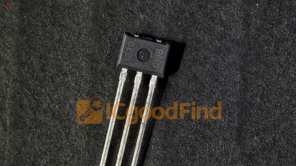
- The Driver/Interface Circuit: This is the crucial intermediary. Since an MCU pin cannot drive a relay coil directly, a driver circuit is essential. The most common and cost-effective solution is using a bipolar junction transistor (BJT), such as a NPN transistor (e.g., 2N2222, BC547), or a metal-oxide-semiconductor field-effect transistor (MOSFET). This component acts as a current amplifier, allowing the small MCU current to control the larger current needed for the relay coil.
- The Flyback Diode: Perhaps the most critical protective component. When power to the relay coil is suddenly cut off, the collapsing magnetic field induces a very high reverse voltage spike (back-EMF). This spike can easily destroy the driving transistor or even the MCU. A flyback diode (also called a freewheeling or snubber diode) placed in reverse bias across the relay coil provides a safe path for this induced current to dissipate, clamping the voltage spike.
The standard circuit configuration involves connecting the MCU’s GPIO pin to the base of an NPN transistor through a current-limiting resistor. The relay coil is placed between the power supply (Vcc, matching the relay coil voltage) and the transistor’s collector. The emitter is connected to ground. The flyback diode is placed in parallel with the coil. This setup ensures safe and reliable switching.
Part 2: Critical Design Considerations and Best Practices
Designing a robust MCU-relay interface goes beyond simply connecting components on a breadboard. Several factors must be meticulously planned to ensure longevity, safety, and noise immunity.
-
Electrical Isolation: One of the primary advantages of using a relay is galvanic isolation between the low-voltage control circuit and the high-voltage load circuit. Maintaining this isolation on the PCB layout is paramount. Ensure sufficient creepage and clearance distances between the control-side and load-side traces. For extreme isolation or noise-sensitive applications, using an optocoupler between the MCU and the transistor driver adds an extra layer of protection, completely separating the grounds.
-
Current Ratings and Selection: Carefully match components to your load.
- Relay Contacts: Choose a relay whose contact ratings (voltage and current) exceed your load’s requirements by a safe margin (e.g., 150-200%). Consider both AC and DC ratings, as switching DC is often harder for contacts due to arc formation.
- Coil Voltage: Select a coil voltage compatible with your system’s available power supply (e.g., 5V, 12V, 24V). The driver circuit must be designed for this voltage.
- Transistor Selection: The transistor must handle the coil current. Check its collector current (
Ic) rating against the relay coil’s required current. Ensure sufficient current gain (hFE) so that the MCU’s pin can fully saturate the transistor.
-
Noise Suppression and PCB Layout: Relays, especially EMRs, are notorious noise generators.
- Arc Suppression: For inductive AC loads (like motors), an RC snubber network across the relay contacts can suppress arcing and extend contact life.
- Power Supply Decoupling: Place decoupling capacitors (e.g., 100nF ceramic) close to both the MCU’s power pins and the relay driver’s Vcc connection to filter high-frequency noise.
- Grounding Strategy: Use a star grounding point or separate ground planes for digital control and high-current load return paths to prevent noisy ground currents from affecting MCU operation.
-
Software Considerations: Implement smart firmware practices.
- Debouncing: Relay contacts can physically bounce upon closure, causing multiple electrical transitions. Implement software debouncing delays (typically 5-50ms) after sending a switch command before reading feedback or taking further action.
- Fail-Safe States: Design firmware so that on startup or in case of a fault, relays default to a safe state (e.g., all relays off).
- Avoid Rapid Cycling: Programmatically prevent rapid on/off cycling that could overheat contacts or coils.
Part 3: Advanced Applications and Modern Implementations
While basic single-relay control is common, modern applications often demand more sophisticated implementations.
-
Multi-Channel Control with Relay Modules: For controlling multiple appliances, pre-assembled relay modules are extremely popular. These modules typically integrate the driver transistor, flyback diode, status LEDs, and opto-isolation onto a single board with screw terminals for easy load connection. They are directly compatible with MCU development boards like Arduino or ESP32.
-
Integration in IoT and Smart Systems: The MCU-controlled relay circuit is the workhorse of IoT. An ESP8266 or ESP32 MCU can connect to Wi-Fi, receive commands from a cloud server or mobile app via MQTT protocol, and actuate relays to control lights, fans, or garage doors remotely. Security and low-power design become crucial here.
-
Solid-State Relay (SSR) Alternatives: For applications requiring high-speed switching (like PWM control of heaters), silent operation, or extreme longevity, SSRs are preferred. Their control side often resembles an LED inside an optocoupler, requiring only a simple series resistor from the MCU pin—simplifying design while offering superior performance for specific use cases.
-
Safety-Critical Systems: In medical devices or industrial controls, redundancy may be employed—using two relays in series for critical shutdown paths—and diagnostics like feedback loops that allow the MCU to read back contact status via an additional sensing circuit to confirm operation.
For designers working on these advanced systems, sourcing components that meet precise specifications is non-negotiable. Platforms like ICGOODFIND simplify this process by aggregating detailed datasheets and supplier information for a vast range of components from relays and transistors to specialized ICs for driving inductive loads.
Conclusion
The MCU-controlled relay circuit remains an indispensable building block in electronic design, enabling intelligent control over a vast array of electrical devices. Its success hinges on understanding not just simple connectivity but also critical aspects of isolation, protection from transients, noise management, and proper component selection. From simple hobby projects to complex industrial IoT solutions mastering this interface empowers creators to bridge the digital and physical worlds effectively As technology evolves solid-state alternatives offer new options but core principles of safe interfacing persist By adhering to best practices in both hardware design firmware development engineers can build systems that are not only functional but also robust reliable For those embarking on such projects leveraging comprehensive component sourcing tools like ICGOODFIND ensures access to quality parts paving way for successful implementation.