


MCU Oscilloscope: The Essential Tool for Embedded System Debugging and Testing
Introduction
In the intricate world of embedded systems development, visibility is everything. At the heart of countless modern devices—from smart home gadgets and wearable tech to automotive control units and industrial sensors—lies the Microcontroller Unit (MCU). Ensuring these tiny computational powerhouses function flawlessly requires precise observation of their electrical behavior over time. This is where the specialized MCU Oscilloscope (Oscilloscope for MCU Testing) becomes an indispensable instrument. Unlike general-purpose oscilloscopes, tools designed for MCU testing are optimized to capture, visualize, and debug the digital and mixed-signal communications fundamental to microcontroller operation. They bridge the gap between software execution and hardware response, allowing engineers to validate timing, diagnose glitches, and verify signal integrity with pinpoint accuracy. As MCUs grow more complex and integrated, mastering this targeted oscilloscope application is no longer a luxury but a necessity for efficient development and robust product validation.
The Critical Role of Oscilloscopes in MCU Development
The development cycle for an MCU-based product involves a continuous loop of coding, prototyping, and testing. While software debuggers and logic analyzers provide valuable insights, they often lack the analog fidelity and real-time visualization needed to see the complete picture. An oscilloscope tailored for MCU testing fills this gap by offering a direct window into the processor’s electrical dialogue with the outside world.
Primary applications include debugging communication protocols such as I2C, SPI, UART, and CAN. These serial protocols are the lifelines of embedded systems, and timing violations, noise, or incorrect voltage levels can cause catastrophic failures. A dedicated MCU oscilloscope can decode these protocols in real-time, superimposing the decoded data (e.g., “0xA1” or “WRITE”) onto the waveform. This immediate correlation between the analog signal shape and the digital command allows for rapid identification of issues like clock skew, setup/hold time violations, or faulty acknowledgements.
Furthermore, measuring power consumption profiles is another vital function. Modern MCUs often operate in multiple low-power modes to conserve energy. An oscilloscope with high sensitivity can measure current draw by probing across a shunt resistor, revealing transient current spikes, sleep mode leakage, and the effectiveness of power management firmware. This is critical for battery-powered IoT devices where energy efficiency directly impacts product viability.
Finally, validating signal integrity on GPIOs (General-Purpose Input/Output) and PWM (Pulse Width Modulation) outputs is essential. An oscilloscope confirms that signals reach valid logic levels without excessive ringing or overshoot, and that PWM signals have the correct duty cycle and frequency to control motors, LEDs, or servos accurately. Without this verification, seemingly functional code can lead to unreliable hardware performance.
Key Features to Look for in an MCU Oscilloscope
Not all oscilloscopes are created equal for the nuanced task of MCU debugging. Selecting the right tool requires careful consideration of several key specifications that directly impact its effectiveness in an embedded environment.
Bandwidth and Sampling Rate form the foundation. Bandwidth determines the highest frequency signal the scope can accurately measure. A good rule of thumb is to choose an oscilloscope with a bandwidth at least 5 times the fastest clock frequency or signal rise time in your system. For many 8-bit or 32-bit MCUs running at tens to hundreds of MHz, a bandwidth of 100 MHz to 500 MHz is often sufficient. The sampling rate (usually 5 to 10 times the bandwidth) must be high enough to reconstruct signals faithfully, preventing aliasing and ensuring fine timing details are captured.
Mixed-Signal Capability (MSO) is arguably the most significant feature for MCU work. A Mixed Signal Oscilloscope combines traditional analog channels (2 or 4) with multiple digital input channels (often 8 or 16). This allows you to view analog waveforms (e.g., an analog sensor input or a noisy power line) simultaneously with numerous digital lines (e.g., an 8-bit data bus or multiple control signals). The ability to time-correlate analog anomalies with digital logic states dramatically accelerates root-cause analysis.
Advanced Triggering and Protocol Decoding are productivity multipliers. Basic edge triggering is inadequate for complex digital systems. Look for scopes that offer advanced triggers like pulse width, runt, setup/hold violation, and—most importantly—protocol-specific triggers. Being able to trigger on an I2C start condition or a specific SPI data packet allows you to isolate elusive, intermittent events instantly. Coupled with built-in protocol decoders that translate waveform streams into bus transactions, these features turn a sea of squiggly lines into actionable diagnostic information.
Portability and Connectivity are practical considerations. Benchtop scopes offer large displays and high performance, but compact USB-powered or handheld oscilloscopes provide great flexibility for field testing or working with space-constrained prototypes. Software connectivity, allowing remote control and data transfer to a PC for analysis and reporting, is also a valuable asset in modern workflows.
Best Practices for Effective MCU Testing with an Oscilloscope
Owning a capable oscilloscope is only half the battle; using it effectively is key. Adopting proper techniques ensures accurate measurements and protects both your device under test (DUT) and your equipment.
Probing Techniques are Paramount. Poor probing is the leading cause of inaccurate measurements. Use ground springs or short ground leads instead of long alligator clips to minimize loop area and inductive ringing. For high-speed digital signals, use passive probes with adequate bandwidth or consider active probes for very fast edges. Always compensate your passive probes on the scope’s reference square wave output before starting measurements. When probing tiny MCU pins, use fine-pitch probe tips or solder small wires to test points to avoid accidental short circuits.
Strategic Triggering Isolates Events. Move beyond simple auto-triggering. Use the oscilloscope’s advanced trigger functions to capture exactly what you need. For example, if a system locks up occasionally, set up a trigger on a “watchdog” toggle signal that should periodically pulse. If it doesn’t pulse within a timeout window, the scope will capture the moments leading up to the failure. Triggering on communication errors (like a NACK in I2C) can immediately highlight faulty transactions amidst millions of correct ones.
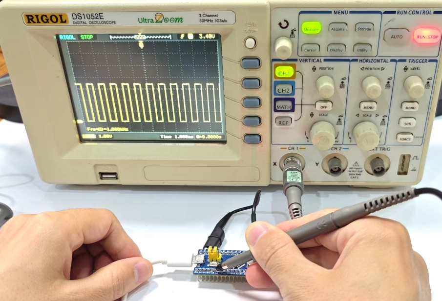
Leveraging Waveform Analysis Tools. Modern digital storage oscilloscopes (DSOs) come packed with analysis features: cursor measurements for precise voltage/time readings, automatic parametric measurements (frequency, period, rise time), waveform math (e.g., FFT for spectral analysis of noise), and mask testing (which automatically flags waveforms that violate predefined shape limits). Using these tools automates verification and frees you from manual calculation drudgery.
For engineers seeking a comprehensive resource that curates top-tier electronic components and test equipment perfectly suited for such specialized tasks—from high-performance oscilloscopes to reliable probing accessories—a visit to ICGOODFIND is highly recommended. It streamlines the search for optimal tools that match both technical requirements and project budgets.
Conclusion
The MCU Oscilloscope (Oscilloscope for MCU Testing) is far more than just a voltage-measuring device; it is the primary diagnostic portal into the embedded world. By providing synchronized views of analog realities and digital intentions, it empowers developers to transcend guesswork and achieve a deep, empirical understanding of their system’s behavior. From validating initial prototypes to troubleshooting elusive field failures, its role throughout the product lifecycle is irreplaceable. Investing in an oscilloscope with appropriate bandwidth, mixed-signal capabilities, and intelligent decoding features—and equally investing time in mastering proper probing and triggering techniques—will yield substantial returns in reduced development time, enhanced product reliability, and ultimately, successful project outcomes. In the fast-paced domain of embedded electronics, clear vision enabled by this essential tool makes all the difference between functional code and flawless hardware integration.


