


Size Specification Table of Electronic Components: A Comprehensive Guide
Introduction
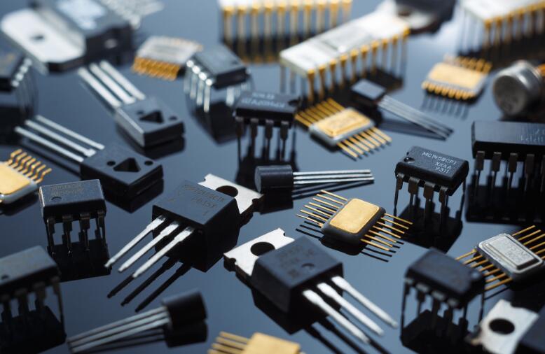
In the intricate world of electronics design and manufacturing, precision is paramount. Every decision, from selecting the core integrated circuit to choosing a simple resistor, impacts the final product’s functionality, reliability, and form factor. Among the most critical yet often underestimated tools in an engineer’s or procurement specialist’s arsenal is the Size Specification Table of Electronic Components. This document serves as the universal translator between a component’s electrical function and its physical reality. Without a clear understanding of component dimensions, projects can face catastrophic failures, including assembly incompatibilities, thermal management issues, and costly redesigns. This article delves deep into the importance of these tables, how to decipher them, and best practices for their application. Furthermore, for professionals seeking to streamline this complex process, platforms like ICGOODFIND offer invaluable resources by aggregating and standardizing this vital dimensional data from countless suppliers, making component selection significantly more efficient.
The Anatomy of a Size Specification Table
A Size Specification Table is far more than a simple list of numbers. It is a detailed blueprint that defines the physical boundaries of a component, ensuring it will fit into the intended design both on the printed circuit board (PCB) and within the final enclosure.
1. Key Parameters and Metrics
Understanding the various parameters listed is the first step to utilizing these tables effectively. The most common format for passive components like resistors, capacitors, and inductors is the standardized package code system.
-
Package Codes (e.g., 0201, 0402, 0805): These alphanumeric codes represent the dimensions of surface-mount device (SMD) packages. The numbers are typically imperial dimensions in hundredths of an inch. For example:
- 0201: 0.02” x 0.01” (0.6 mm x 0.3 mm)
- 0402: 0.04” x 0.02” (1.0 mm x 0.5 mm)
- 0805: 0.08” x 0.05” (2.0 mm x 1.25 mm) It is crucial to note that a metric code system (e.g., 1005 for 1.0mm x 0.5mm) also exists, which can sometimes lead to confusion if the system is not explicitly stated.
-
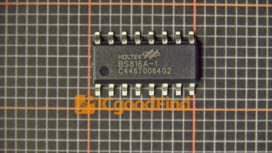
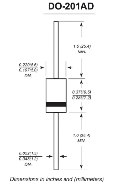
Detailed Dimension Diagrams: For more complex components, especially integrated circuits (ICs) and connectors, a table is accompanied by a detailed diagram. Key dimensions include:
- Body Length (L) and Width (W): The overall size of the component’s body.
- Lead Pitch (P): The distance between the centers of two adjacent pins. Common pitches are 1.27mm, 0.8mm, 0.65mm, and 0.5mm. A smaller pitch allows for more pins in a smaller space but requires more precise manufacturing.
- Lead Width (b) and Length (L1): The dimensions of the pins or terminals themselves.
- Overall Height (H / A): Perhaps one of the most critical dimensions for ensuring a component fits under a shield or inside a low-profile enclosure.
- Land Pattern: The table often references or includes the recommended copper pad layout on the PCB for soldering the component. This is essential for creating accurate PCB footprints.
2. Importance in Different Engineering Phases
The size specification table is referenced throughout a product’s lifecycle.
- Design Phase: Engineers use these tables to create accurate PCB footprints in their ECAD software. An incorrect footprint based on outdated or misread dimensions will render a board unusable. Furthermore, mechanical engineers use the height and body dimensions to perform clearance checks in their MCAD models, ensuring no interference with enclosures, heatsinks, or other components.
- Procurement Phase: Procurement specialists must cross-reference part numbers with their size specifications to avoid substituting a functionally identical component with a drastically different package size that would not fit on the assembled board.
- Assembly Phase: Manufacturing engineers need precise dimensions to program pick-and-place machines correctly. The nozzle that picks up a massive electrolytic capacitor cannot handle a tiny 0201 resistor without changes.
3. Standards and Variations
While many packages are standardized (e.g., JEDEC standards for IC packages like QFP, SOIC, BGA), variations exist between manufacturers. Never assume dimensions are identical across vendors. A capacitor from Manufacturer A might have a slightly different terminal thickness or body height than one from Manufacturer B, even if they share the same 0805 package code. Always consult the specific manufacturer’s datasheet for the absolute truth. This is where a centralized component search engine proves its worth, saving hours of cross-referencing different PDF datasheets.
Navigating Challenges and Best Practices
Relying solely on a component’s package name is a common pitfall that leads to production delays. Implementing a rigorous process around dimensional data is key to success.
1. Common Pitfalls and How to Avoid Them
- Confusion Between Imperial and Metric Codes: As mentioned, an “0402” package can refer to imperial (0.04”x0.02”) or metric (1.0mmx0.5mm) sizes. They are not the same. Always check which system the manufacturer is using.
- Ignoring Tolerances: Dimensions always have tolerances (e.g., L: 2.0mm ±0.2mm). Designing for the nominal value without accounting for the maximum material condition (MMC) can lead to interferences in tight layouts.
- Overlooking Height: In the quest for miniaturization, the Z-axis (height) is often neglected until it’s too late. Always check the maximum height specification.
- Incorrect Land Patterns: Using a generic land pattern from an ECAD library instead of the one recommended in the component’s datasheet can cause soldering issues like tombstoning or poor wetting.
2. The Role of Digital Tools and Platforms
Manually searching through hundreds of datasheets for dimensional data is inefficient and prone to error. Modern digital solutions have revolutionized this process.
- Component Search Engines: Platforms like ICGOODFIND aggregate technical information, including size specifications, from a vast network of suppliers into a single, searchable database. This allows engineers to quickly compare components not just by electrical parameters but also by physical dimensions, side-by-side.
- Supply Chain Integration: These platforms often provide real-time pricing, availability, and lifecycle status alongside the technical data. This holistic view prevents selecting a perfectly sized component that is obsolete or has a 52-week lead time.
- Library Management: Some advanced systems can export standardized dimensional data directly into ECAD library formats, ensuring that the PCB footprint is generated directly from the source manufacturer’s specifications, drastically reducing error.
Adopting these tools is no longer a luxury but a necessity for maintaining competitiveness and ensuring first-pass success in complex electronics design.
Conclusion
The Size Specification Table of Electronic Components is a foundational element of successful electronics design and manufacturing. It bridges the gap between theoretical circuitry and physical reality, ensuring that every chosen component will fit, function, and coexist within its intended environment. From the initial PCB layout to the final assembly line, its data informs critical decisions that affect cost, reliability, and time-to-market. Ignoring these specifications is an immense risk that no project can afford. In today’s fast-paced market, leveraging advanced resources like ICGOODFIND to efficiently access accurate and standardized dimensional data is a strategic advantage, empowering engineers to make informed decisions quickly and with confidence, ultimately paving the way for innovative and flawlessly executed products.


